

Top-emitting OLED device with improved performance
a technology of organic light and diode, which is applied in the direction of organic semiconductor devices, discharge tubes/lamp details, discharge tubes luminescnet screens, etc., can solve the problems of small fraction of generated light available for viewing, 80% of generated light is trapped within the device, and the display is at risk of operational degradation
- Summary
- Abstract
- Description
- Claims
- Application Information
AI Technical Summary
Benefits of technology
Problems solved by technology
Method used
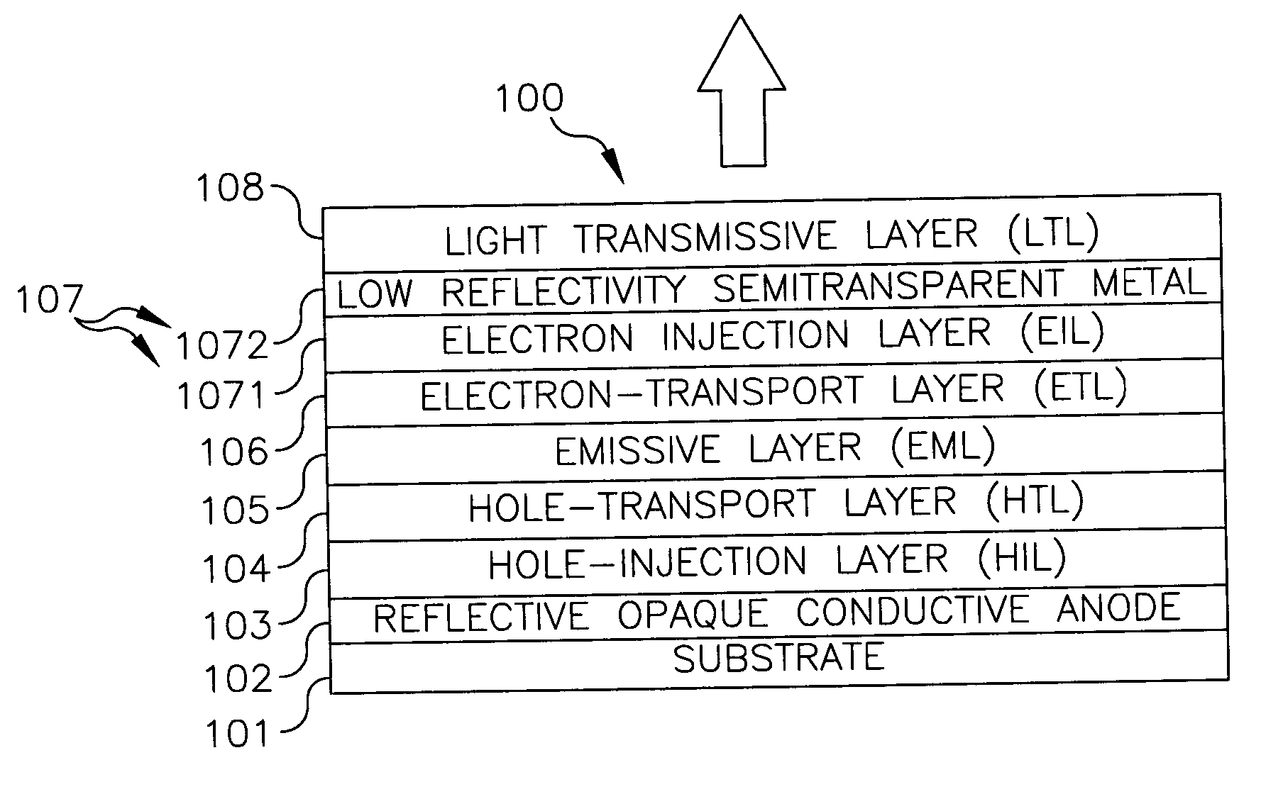
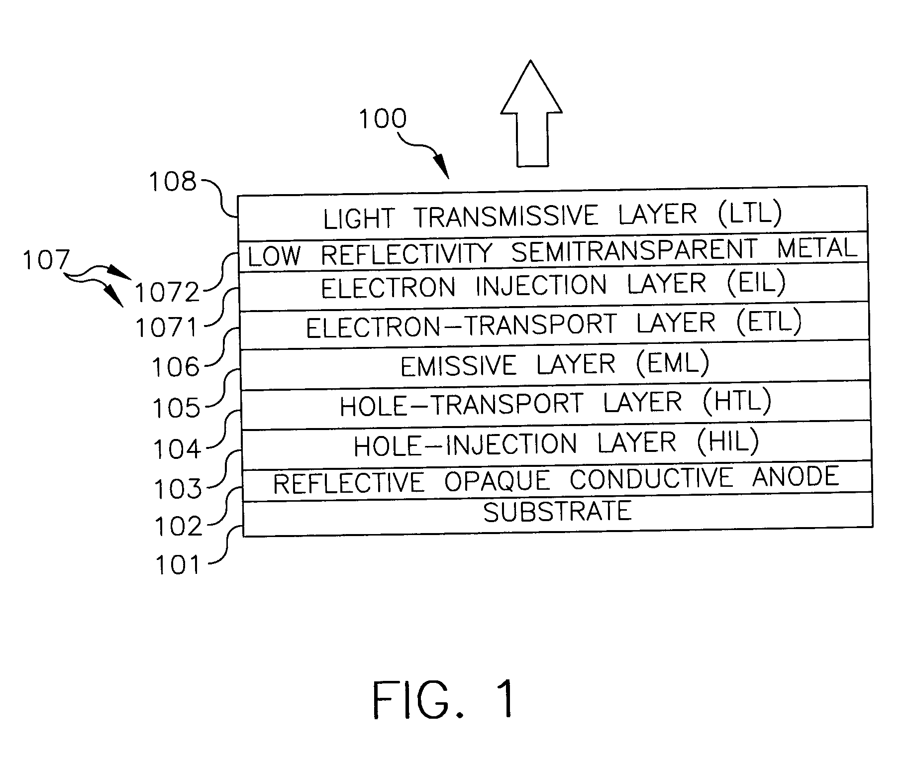
Image

Examples
example 1
[0065] A REF. OLED, device 2A, was made on a glass substrate having a 70 ohm / sq ITO layer as the anode. A MC-OLED, device 2B, was fabricated on glass substrate having a high reflectivity anode layer of Ag. Each of the devices has identical EML / ETL and the structures were optimized for maximization of light emission. The device 2B has a semitransparent Ag cathode and a LTL of Alq on the Ag cathode. Thus, device 2B is a MC-OLED both electrodes of which constituted of a high reflectivity metal. The devices have the following layer structures: [0066] 2 A: Glass (1.1 mm) / ITO (42 nm) / CFx (1 nm) / NPB (115 nm) / Alq (60 nm) / MgAg (22 nm)—(PR040830-1A) [0067] 2 B: Glass (1.1 mm) / Ag (80 nm) / MoOx (2.5 nm) / NPB (45 nm) / Alq (60 nm) / Li (0.5 nm) Ag (20 nm) / Alq (80 nm)—(PR040817-1F)
[0068] The performance of the diodes including the shift of emission wave length with viewing angle (angular characteristic) is presented in Table 2:
TABLE 2EfficiencyPeak wavePeak waveDrive(cd / A)length (nm)length (nm)Devic...
example 2
[0070] A device of the present invention, Inventive OLED, device 3C, was fabricated on glass substrate having a pure Ag anode layer. This device has a semitransparent Yb cathode and was provided with a LTL of ITO on the Yb layer. The device has the following layer structure: [0071] 3 C: Glass (1.1 mm) / Ag (80 nm) / MoOx (2.5 nm) / NPB (45 nm) / Alq (60 nm) / Li (0.5 nm) / Yb (20 nm) / ITO (32 nm)—(PR040820-1C)
[0072] The performance including angular characteristic of the device 3C is presented in Table 3 along with that of the REF. OLED, device 2A, of Table 2.
TABLE 3EfficiencyPeak wavePeak waveDrive(cd / A)length (nm)length (nm)Devicevoltageon-axison-axisoff-axisDeviceType(V)(0°)(0°)(60°)2AREF. OLED7.53.35285233CInventive6.83.3525526OLED
[0073] It can be seen from Table 3 that the REF. OLED, device 2A, and the Inventive OLED, device 3C, have same luminance. The device 3C has slightly lower drive voltage compared to the device 2A. This might be due to higher hole injection efficiency of the Ag / Mo...
example 3
[0074] A series of OLEDs, devices 4A through 4D, was made with varying thickness of a conductive LTL of sputtered ITO. The Li and the Yb layers were fixed and the conductive ITO layer on the Yb was varied. Thus the cathode structure comprising the Li, Yb and ITO was varied in this series. All other layers of all these devices were identical. The devices have the following layer structure: [0075] Glass (1.1 mm) / Ag (80 nm) / MoOx (2.5 nm) / NPB (45 nm) / Alq (60 nm) / Li (0.5 nm) / Yb (20 nm) / ITO (varying)—(PR0400817-1)
[0076] The performance including angular characteristic of the devices 4A through 4D is presented in Table 4.
TABLE 4EfficiencyPeak wavePeak waveITODrive(cd / A)length (nm)length (nm)thicknessvoltageon-axison-axisoff-axisDevice(nm)(V)(0°)(0°)(60°)4A07.42.35425324C427.24.25275274B707.55.15445034D987.53.3561523
[0077] It was believed that the lateral conductivity of cathode structure and the device voltage would improve upon application of the ITO layer. The drive voltage of these O...
PUM
 Abstract
Description
Claims
Application Information