Laser oscillator and method of estimating the lifetime of a pump light source

a technology of laser oscillator and light source, which is applied in the direction of laser details, semiconductor lasers, electrical apparatus, etc., can solve the problems of drop in the accuracy of lifetime estimation, and achieve the effect of accurately estimating simple configuration and accurate estimation of the lifetime of the pump light sour

Inactive Publication Date: 2006-07-20
FANUC LTD
View PDF5 Cites 8 Cited by
  • Summary
  • Abstract
  • Description
  • Claims
  • Application Information

AI Technical Summary

Benefits of technology

[0022] Further, in the method of estimation of the lifetime of the pump light source of the laser oscillator according to the present invention, preferably, in the step of adjusting to the predetermined intensity, the method of output of the laser is pulse output, and the step of measuring the current value measures the value of the current when the fluctuation of the signal output by the power sensor remains within a predetermined range for a predetermined period. By measuring the value of the current in the state where the output of the laser light is substantially constant and stable, it is possible to estimate the lifetime of the pump light source more accurately. Note that when generating laser light by the pulse method, the signal output by the power sensor means a signal corresponding to the intensity of the laser light measured by the power sensor during output of the laser light or the average output signal in a period of a certain cycle including a period of output of the laser light and an idle period in the same durations.
[0023] As explained above, it is possible to obtain a laser oscillator able to estimate the lifetime of the pump light source by a simple configuration. Further, it is possible to accurately estimate the lifetime of the pump light source.

Problems solved by technology

A wavelength shift of the laser diode therefore is also a factor causing a drop in the accuracy of estimation of lifetime.

Method used


Image

  • Laser oscillator and method of estimating the lifetime of a pump light source
  • Laser oscillator and method of estimating the lifetime of a pump light source
  • Laser oscillator and method of estimating the lifetime of a pump light source

Examples


second embodiment

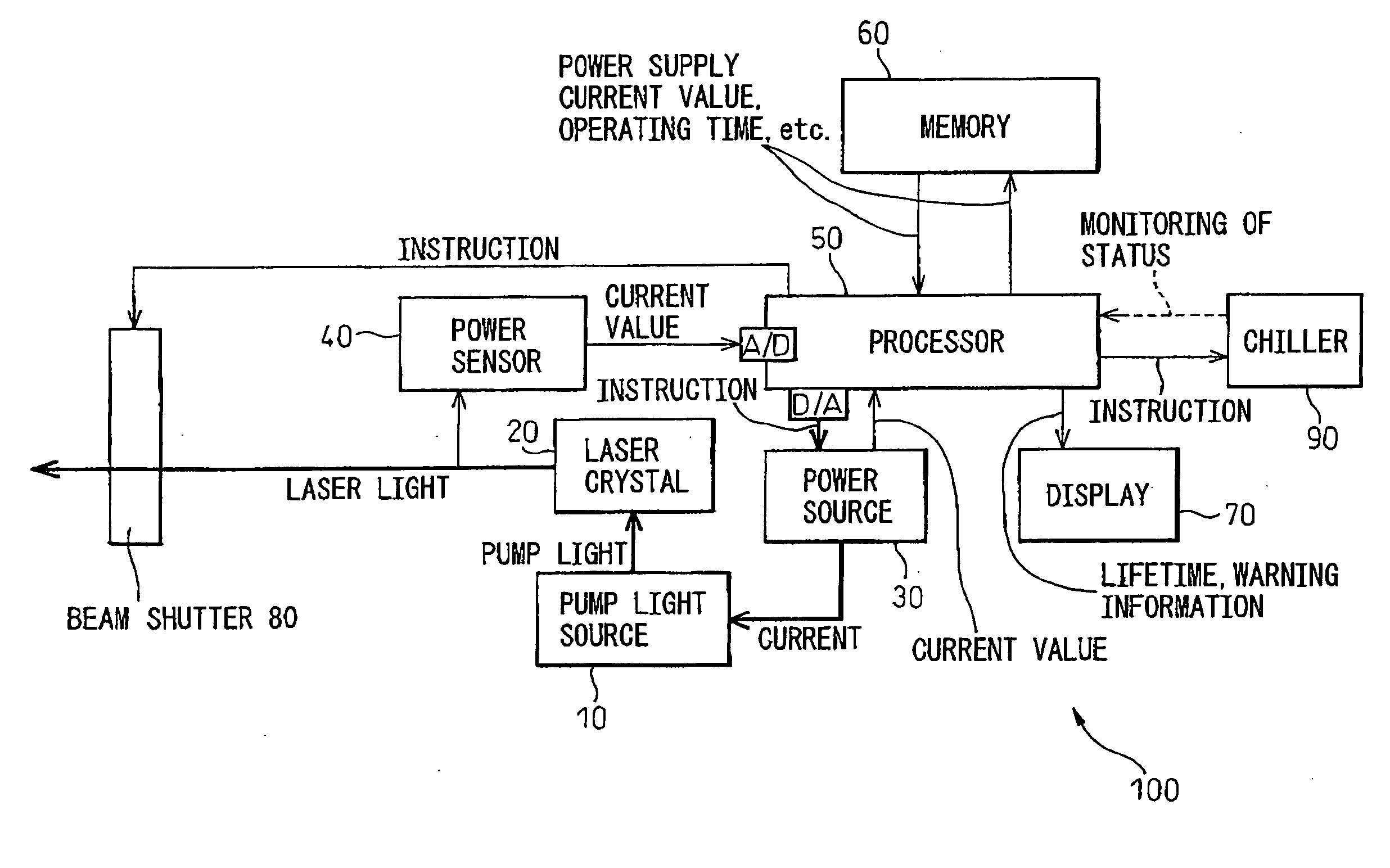
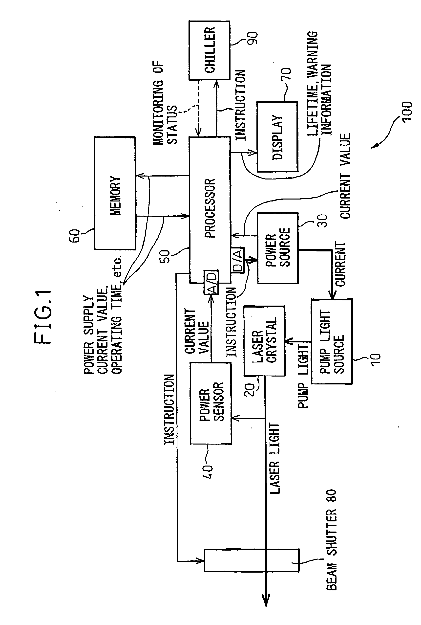
[0083]FIG. 3 is a view of the configuration of a laser oscillator according to the present invention.

[0084] Parts similar to FIG. 1 are assigned the same notations. The configuration shown in FIG. 3 differs from the configuration shown in FIG. 1 in that, in the configuration shown in FIG. 3, a sub processor 55 is separately provided for independently handling the functions of the feedback loop for stabilizing the output laser light in the functions of the processor 50 shown in FIG. 1.

[0085] The sub processor 55 may be a processing unit built into the laser unit or may be an external processing unit such as a personal computer designed to be able to communicate with the laser unit and the processor 51. Further, the sub processor 55 may be configured as a circuit integral with the laser light current measurement circuit of the power sensor 40. In this configuration, when the sub processor 55 receives an instruction to turn on the power from the processor 51, it issues an instruction ...

third embodiment

[0088]FIG. 4 shows an example of the configuration of a laser oscillator 300 according to the present invention.

[0089] In the same way as above, parts similar to the parts shown in FIG. 1 or FIG. 3 are assigned the same notations. The configuration shown in FIG. 4 differs from the configuration shown in FIG. 3 in that, in the configuration shown in FIG. 4, the pump light source 10 has a plurality of sub light sources 15 and the power source 30 has a plurality of sub power sources 35.

[0090] In this example of the configuration, the pump light source 10 is comprised of a plurality of laser diodes or a plurality of laser diode arrays, that is, a plurality of sub light sources 15. For example, each sub light source 15 is an individual laser diode, and a plurality of these laser diodes are arranged in for example a single row to form a laser diode array. The pump light source 10 may be designed to provide a plurality of laser diode arrays as the sub light sources 15, arrange the laser d...


PUM


Abstract

A laser oscillator enabling estimation of the lifetime of the pump light source by a simple configuration, provided with a pump light source, a power source supplying current to the pump light source, a laser crystal outputting laser light by the pump light emitted from the pump light source, a power sensor receiving laser light generated from the laser crystal and outputting a signal corresponding to the intensity of the laser light, a memory storing the operating time of the laser oscillator, and a processor judging if the signal output by the power sensor satisfies a predetermined condition and, if satisfying the predetermined condition, uses the value of the current supplied by the power source to the pump light source and the operating time stored in the memory to estimate the lifetime of the pump light source.

Description

BACKGROUND OF THE INVENTION [0001] 1. Field of the Invention [0002] The present invention relates to a laser oscillator, more particularly relates to a laser oscillator provided with a function of estimating the lifetime of a pump light source and a method of estimating the lifetime of a pump light source of a laser oscillator. [0003] 2. Description of the Related Art [0004] In a solid state laser oscillator, in particular a laser oscillator using an Nd:YAG crystal etc. as a laser crystal, a lamp or laser diode or other such consumable is used as the pump light source. Since the light source is a consumable, it has to be periodically replaced. Since the lifetimes are not uniform, however, it is necessary to replace the light source while checking its state of emission. However, measuring the output of a lamp or laser diode in a laser oscillator is difficult. Some sort of indicator for determining the replacement time has therefore been required. In particular, when using a pump ligh...

Claims


Application Information

Patent Timeline
Patent Type & Authority Applications(United States)
IPC IPC(8): H01S3/00H01S3/091
CPCH01S3/0014H01S3/0407H01S3/042H01S3/0602H01S3/0941H01S3/1022H01S3/1611H01S3/1643H01S5/0021H01S5/042H01S5/06808
Inventor MACHIDA, HISATADANISHIKAWA, YUJIMIYATA, RYUSUKE
Owner FANUC LTD
Why Eureka
Try Eureka