
Transceiver device capable of calibration and calibration method used by the same

a transceiver and calibration method technology, applied in transmission, substation equipment, electrical apparatus, etc., can solve the problems of direct conversion transceivers suffering from iq mismatch, lo leakage, dc offset, mismatch, etc., to improve calibration accuracy, simple structure, and low cost

Inactive Publication Date: 2006-07-20
SAMSUNG ELECTRONICS CO LTD
View PDF8 Cites 8 Cited by
  • Summary
  • Abstract
  • Description
  • Claims
  • Application Information

AI Technical Summary

Benefits of technology

[0016] The present invention provides an MIMO transceiver device, which can be implemented in a simple structure and at a low cost and improve calibration accuracy, and a calibration method used by the same.

Problems solved by technology

Due to their structural characteristics, related art direct conversion transceivers suffer from IQ mismatch, LO leakage, DC offset, and so on.
IQ mismatch occurs when these conditions for the phase difference between the in-phase signal path and the quadrature signal path and the gain are not met.
Also, a major cause of LO leakage is imperfect performance of a local oscillator.
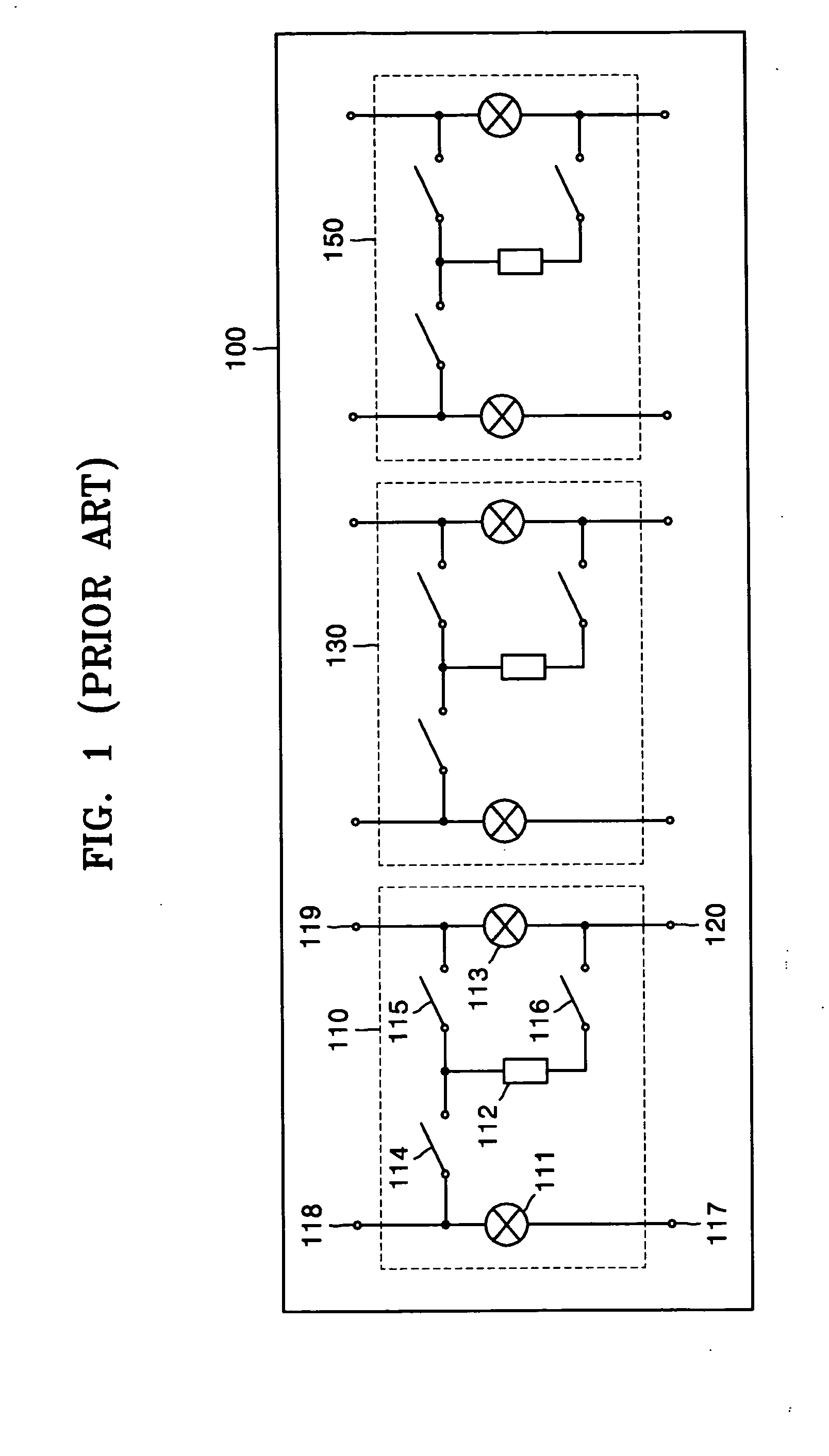
Hence, when the transceiver device 100 is implemented in a single-chip structure, efficiency in the use of space cannot be achieved.
In addition, in case of an asymmetric MIMO transceiver device which does not use one of a plurality of transmission paths, a transmission calibration must be performed, even on the non-used transmission path for a receiving calibration, thereby prolonging the overall calibration time.

Method used


Image

  • Transceiver device capable of calibration and calibration method used by the same
  • Transceiver device capable of calibration and calibration method used by the same
  • Transceiver device capable of calibration and calibration method used by the same

Examples


Embodiment Construction

[0025] The present invention will now be described more fully with reference to the accompanying drawings, in which exemplary embodiments are shown. The invention may, however, be embodied in many different forms and should not be construed as being limited to the embodiments set forth therein; rather, these exemplary embodiments are provided so that this disclosure will be thorough and complete, and will fully convey the concept of the invention to those skilled in the art. Like reference numerals in the drawings denote like elements, and thus their description will omitted.

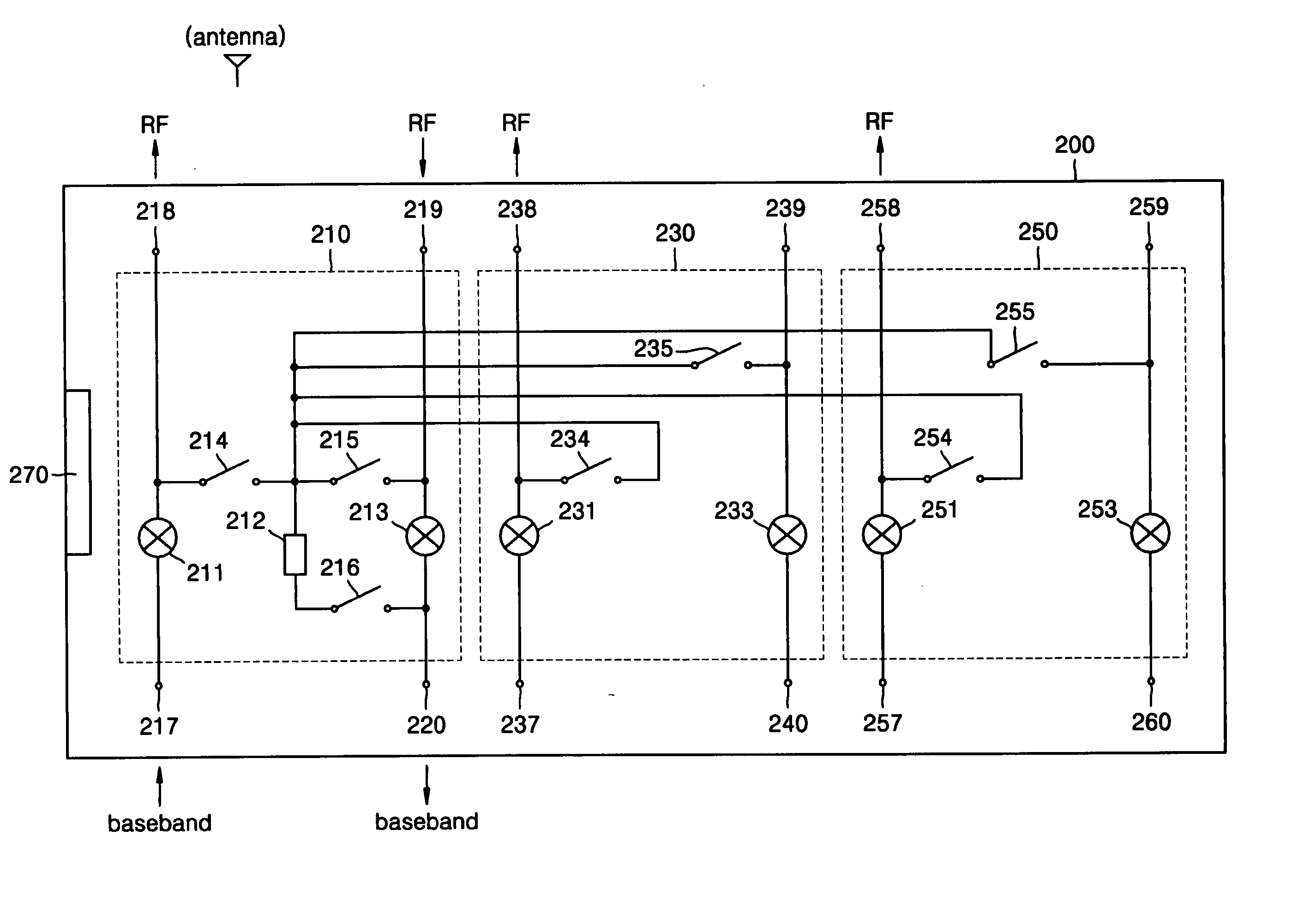
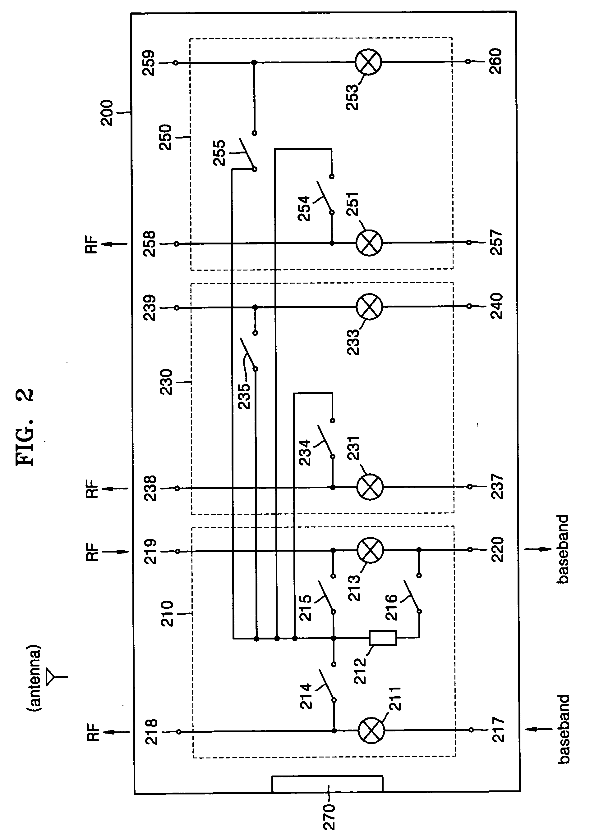
[0026]FIG. 2 is a block diagram of an MIMO transceiver device 200 according to an exemplary embodiment. The MIMO transceiver device 200 is a 3×3 symmetric transceiver device and includes a first transceiver 210, a second transceiver 230, a third transceiver 250, and a digital interface 270. The transceiver device 200 further includes transmission / receiving calibration paths between the first transceiver 210 and...


PUM


Abstract

A transceiver device capable of calibration, and a calibration method used by the transceiver device. The transceiver device includes a reference transceiver, a plurality of remaining transceivers, and a plurality of transmission calibration paths connecting the remaining transceivers to the reference transceiver for transmission calibration of the remaining transceivers. An envelope detector included in the reference transceiver is shared with the remaining transceivers. When implementing a multiple input multiple output (MIMO) transceiver in a single chip, the chip size and manufacturing cost of the MIMO transceiver device can be substantially reduced.

Description

[0001] This application claims priority from Korean Patent Application No. 10-2005-0005003, filed on Jan. 19, 2005, in the Korean Intellectual Property Office, the disclosure of which is incorporated herein in its entirety by reference. BACKGROUND OF THE INVENTION [0002] 1. Technical Field [0003] The present invention relates to a transceiver device having a direct conversion structure and a calibration method used by the transceiver device. [0004] 2. Related Art [0005] In the related art, wireless local area networks (WLANs) are an emerging application of wireless systems. Institute of Electrical and Electronics Engineers (IEEE) 802.11 is a WLAN standard. The 802.11b standard was the first to be commercialized, and the 802.11a standard was developed to address the new needs of the WLAN market. The 802.11a standard uses a frequency of 5 GHz and adopts orthogonal frequency division multiplexing (OFDM) as its modulation scheme. OFDM distributes data among a large number of carriers a ...

Claims


Application Information

Patent Timeline
IPC IPC(8): H04Q7/20
CPCH04B1/0483
Inventor JUNG, WEON-KYOPARK, JOONG-SUKKIM, DAE-YEONKIM, HEE-SEUNG
Owner SAMSUNG ELECTRONICS CO LTD
Learn More