
Modulated optical tweezers

a module and optical technology, applied in the field of modules of optical tweezers, can solve the problems of extending these techniques to larger and more complex systems, requiring larger and more complex arrays of optical traps, interferometric techniques, and substantially more limited in the types of intensity patterns that can be created, so as to facilitate objects' escape, reduce stiffness, and facilitate the effect of objects' escap

Inactive Publication Date: 2006-07-27
NEW YORK UNIV
View PDF13 Cites 28 Cited by
  • Summary
  • Abstract
  • Description
  • Claims
  • Application Information

AI Technical Summary

Benefits of technology

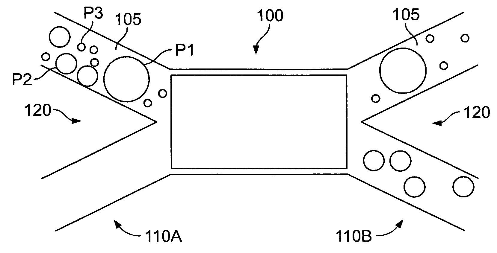
[0012] The present invention relates a variant of optical tweezers in which the trap's stiffness is made to vary with direction. In particular, the modified trap's intensity spreads more broadly in selected directions, thereby reducing its stiffness in those directions, or facilitating alignment of asymmetric objects along those directions. Such modified traps may be used to facilitate objects' escape along selected directions and to orient and rotate non-compact objects. The ability to facilitate objects' escape along selected directions has applications for optical fractionation, in which objects' differing interactions with optical traps are used as the basis for sorting. The ability to orient and rotate non-compact objects may be used in assembling micrometer-scale objects.
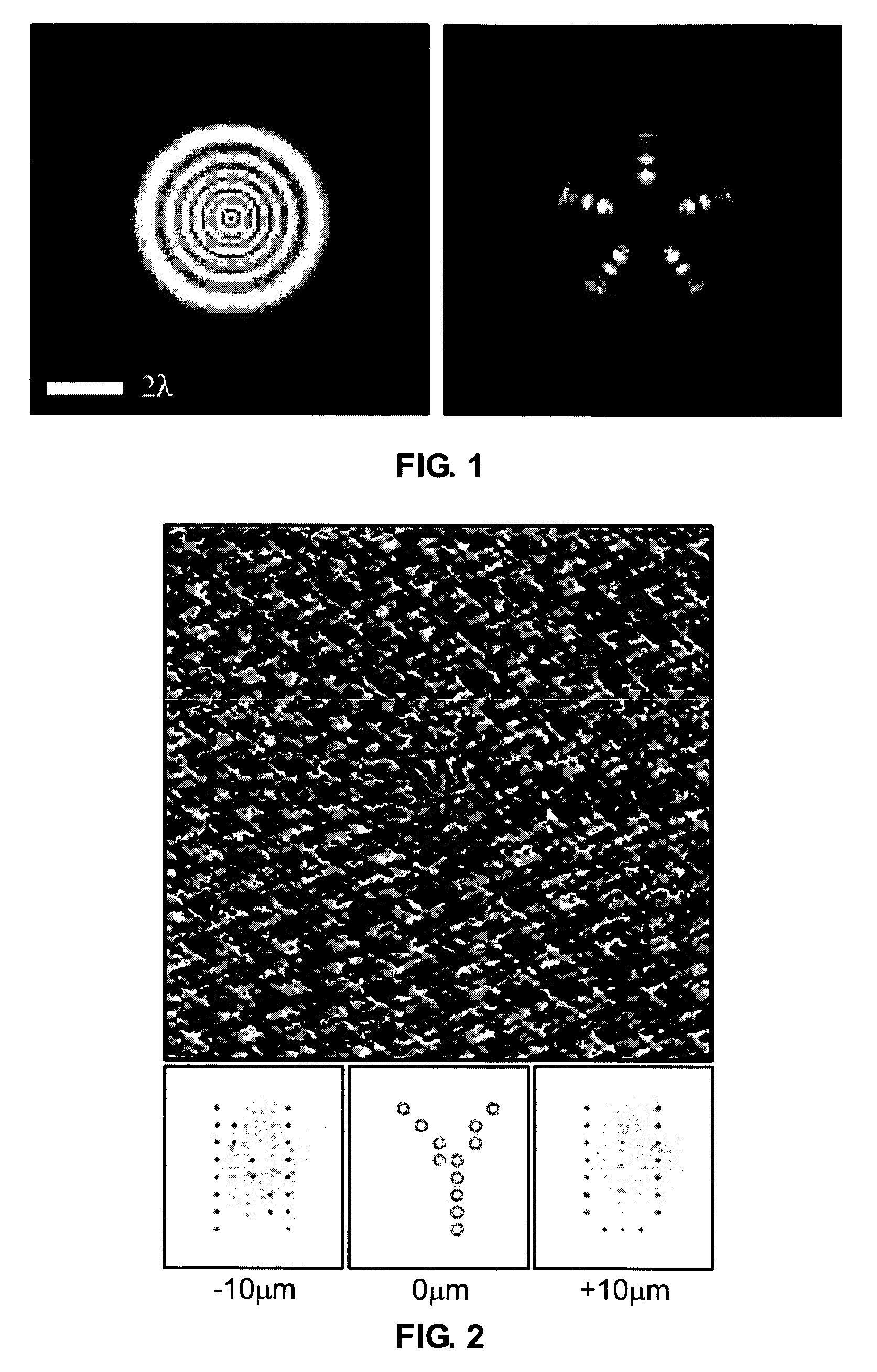
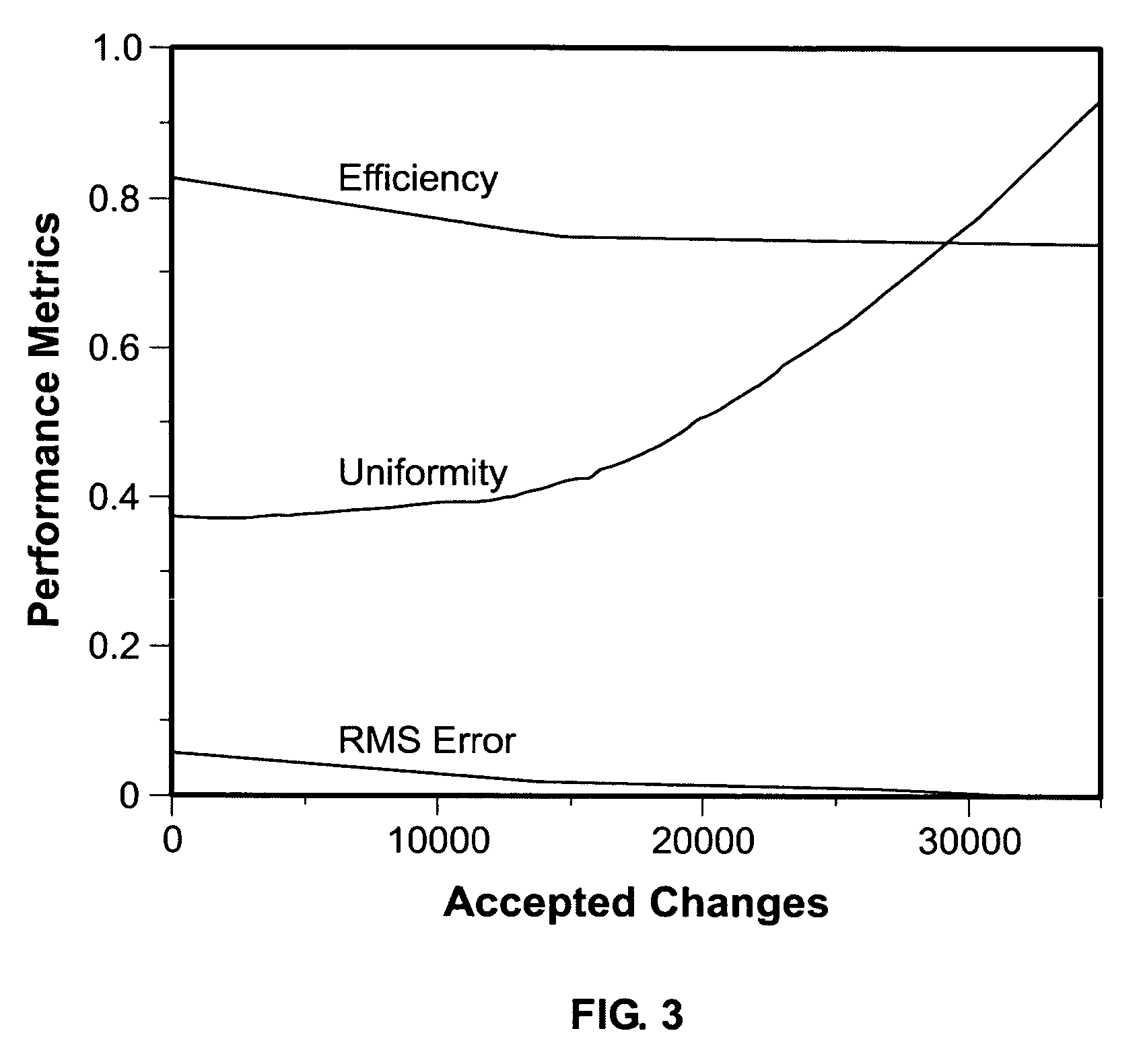
[0014] The present invention also relates to a new class of algorithms for HOT CGH calculation based on direct search and simulated annealing that take advantage of recently introduced metrics to achieve unprecedented trap-formation accuracy and optical efficiency.

Problems solved by technology

Extending these techniques to larger and more complex systems requires larger and more complex arrays of optical traps.
Interferometric techniques can cover larger areas than holographic techniques, but are substantially more limited in the types of intensity patterns that can be created.
In particular, interferometric optical tweezers and optical lattices are limited to periodic structures.
Despite their general efficacy, these algorithms yield traps whose relative intensities can differ substantially from their design values, and typically result in undesirable “ghost” traps.
These problems can become acute for complicated three dimensional trapping patterns, particularly when the same hologram also is used as a mode converter to project multifunctional arrays of optical traps.

Method used


Image

  • Modulated optical tweezers
  • Modulated optical tweezers
  • Modulated optical tweezers

Examples


Embodiment Construction

[0034] Optical traps refer to a type of force exerted by a beam of light to trap and move small objects. In general, these forces fall into two categories: (1) radiation pressure that tends to push objects down the axis of a beam, and (2) optical gradient forces. Optical gradient forces arise because objects develop electromagnetic dipole moments when illuminated by light. Intensity gradients in the light exert forces on these dipole moments whose sign depends on the relative dielectric constants of the object and the surrounding medium. Particles with higher dielectric constants than their surroundings (high-dielectric particles) generally are drawn up by the gradients toward brighter regions while low-dielectric particles are pushed away to darker regions.

[0035] Optical gradient forces provide the basic forces necessary for the single-beam optical trap known as an optical tweezer. An optical tweezer comprises a single beam of light brought to a diffraction-limited focus by a high...


PUM


Abstract

A method and apparatus for selecting a specific fraction from a heterogeneous fluid-borne sample using optical gradient forces in a microfluidic or fluidic system are presented. Samples may range in size from a few nanometers to at least tens of micrometers, may be dispersed in any fluid medium, and may be sorted on the basis of size, shape, optical characteristics, charge, and other physical properties. The selection process involves passive transport through optical intensity field driven by flowing fluid, and so offers several advantages over competing techniques. These include continuous rather than batch-mode operation, continuous and dynamic tunability, operation over a wide range of samples, compactness, and low cost.

Description

[0001] The present invention was supported by the National Science Foundation under Grant Number DBI-0233971, with additional support from Grant Number DMR-0304906.FIELD OF THE INVENTION [0002] The present invention relates to modulated optical tweezers. More particularly, the present invention relates to the use of modulated optical tweezers in a variety of situations. BACKGROUND OF THE INVENTION [0003] Since their introduction a decade ago, optical tweezers have become indispensable tools for physical studies of macromolecular and biological systems. Formed by bringing a single laser beam to a tight focus, an optical tweezer exploits optical gradient forces to manipulate micrometer-sized objects. Optical tweezers have allowed scientists to probe the small forces that characterize the interactions of colloids, polymers and membranes, and to assemble small numbers of colloidal particles into mesoscopic structures. Conventional efforts each required only one or two optical tweezers. ...

Claims


Application Information

Patent Timeline
IPC IPC(8): H05H3/02
CPCB01L3/502715B01L3/502761B01L2200/0636B01L2200/0647B01L2300/0864B01L2400/0454G01N30/00G01N30/02G01N2015/0288G03H1/0808G03H2001/0077G03H2001/0816B01D2015/3895G03H2210/30
Inventor GRIER, DAVID G.
Owner NEW YORK UNIV
Learn More