LED with current confinement structure and surface roughening

Active Publication Date: 2006-07-27
CREELED INC
View PDF14 Cites 100 Cited by
  • Summary
  • Abstract
  • Description
  • Claims
  • Application Information

AI Technical Summary

Benefits of technology

[0010] Briefly, and in general terms, the invention is directed to LEDs having enhanced light extraction features. In one aspect of the invention, the LED includes a p-type layer of material with an associated p-contact, an n-type layer of material with an associated n-contact and an active region between the p-type layer and the n-type layer. The LED further includes a confinement stru

Problems solved by technology

For conventional LEDs with a single out-coupling surface, the external quantum efficiency is limited by t

Method used


Image

  • LED with current confinement structure and surface roughening
  • LED with current confinement structure and surface roughening
  • LED with current confinement structure and surface roughening

Examples


Embodiment Construction

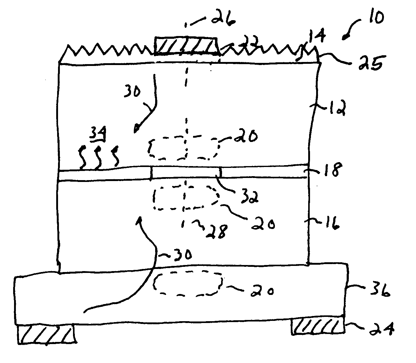
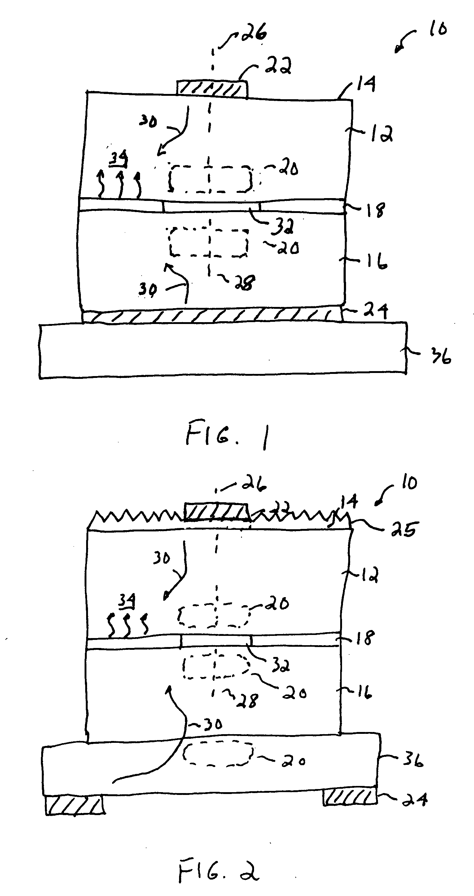
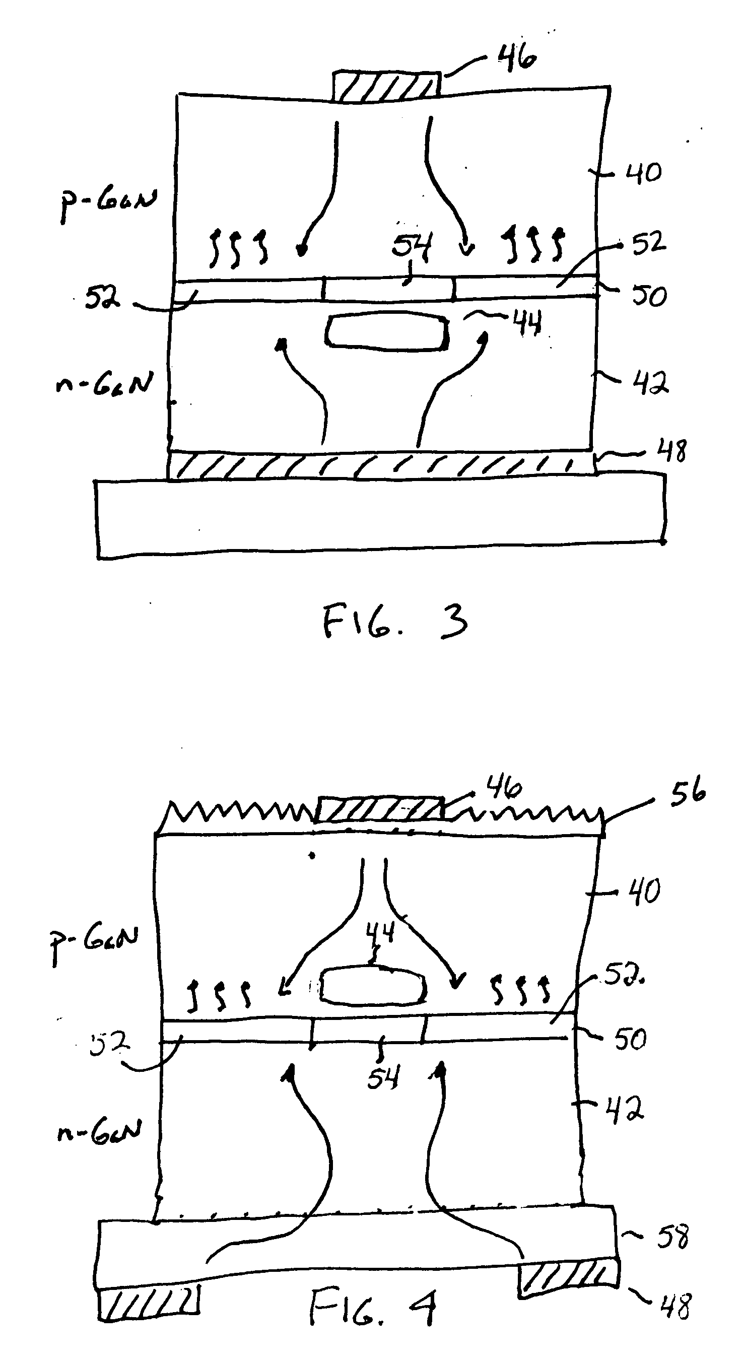
[0022] The present invention provides improved light extraction for light emitting diodes (LEDs) through a confinement structure that is formed within at least one of the p-type layer of material and the n-type layer of material of a base LED structure. The confinement structure is generally aligned with the contact on the top and primary emission surface of the LED and substantially prevents the emission of light from the area of the active region that is coincident with the area of the confinement structure and the top-surface contact. Thus, light that would otherwise emit under and be absorbed by the top-surface contact is redirected to other regions of the active layer and the emitting side where the absorbing affect of the contact is substantially reduced. In a preferred embodiment, the current confinement structure is formed within the based LED structure using ion implantation. The current confinement structure may also be formed in the LED base structure using selective oxid...


PUM


Abstract

An LED having a p-type layer of material with an associated p-contact, an n-type layer of material with an associated n-contact and an active region between the p-type layer and the n-type layer, includes a confinement structure that is formed within one of the p-type layer of material and the n-type layer of material. The confinement structure is generally aligned with the contact on the top and primary emission surface of the LED and substantially prevents the emission of light from the area of the active region that is coincident with the area of the confinement structure and the top-surface contact. The LED may include a roughened emitting-side surface to further enhance light extraction.

Description

BACKGROUND OF THE INVENTION [0001] 1. Field of the Invention [0002] This invention relates to light emitting diodes (LEDs) and more particularly to new structures for enhancing the extraction of light from LEDs. [0003] 2. Description of Related Art [0004] Light emitting diodes (LEDs) are an important class of solid state devices that convert electric energy to light and generally comprise an active layer of semiconductor material sandwiched between two oppositely doped layers. When a bias is applied across the doped layers, holes and electrons are injected into the active layer where they recombine to generate light. Light is emitted omnidirectionally from the active layer and from all surfaces of the LED. [0005] There has been a great deal of recent interest in LEDs formed of Group-III nitride based material systems because of their unique combination of material characteristics including high breakdown fields, wide bandgaps (3.36 eV for GaN at room temperature), large conduction b...

Claims


Application Information

Patent Timeline
IPC IPC(8): H01L33/00H01L33/14H01L33/22
CPCH01L33/145H01L33/22H01L33/405H01L33/42
Inventor DENBAARS, STEVEN P.NAKAMURA, SHUJIBATRES, MAX
Owner CREELED INC
Why Eureka
Try Eureka