Distribution device for two-phase concurrent downflow vessels

a technology of a distribution device and a downflow vessel, which is applied in the direction of combustion air/fuel air treatment, fuel gas production, mixing methods, etc., can solve the problems of friction and pressure drop, and achieve the effect of improving distribution performance, less susceptible to fouling and plugging, and low resistance to liquid flow across the tray

Active Publication Date: 2006-07-27
MORTEN MULLER LTD APS
View PDF7 Cites 54 Cited by
  • Summary
  • Abstract
  • Description
  • Claims
  • Application Information

AI Technical Summary

Benefits of technology

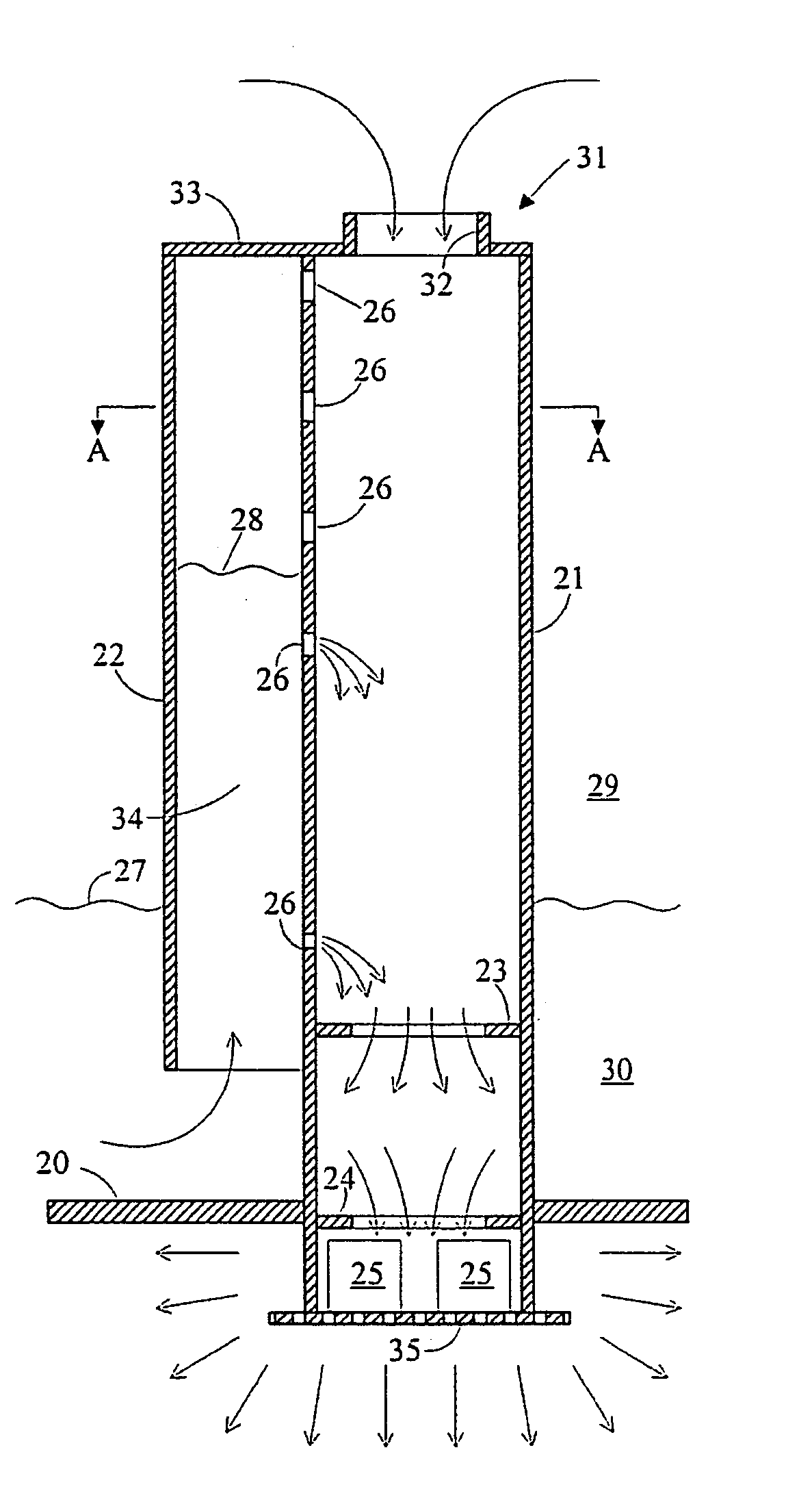
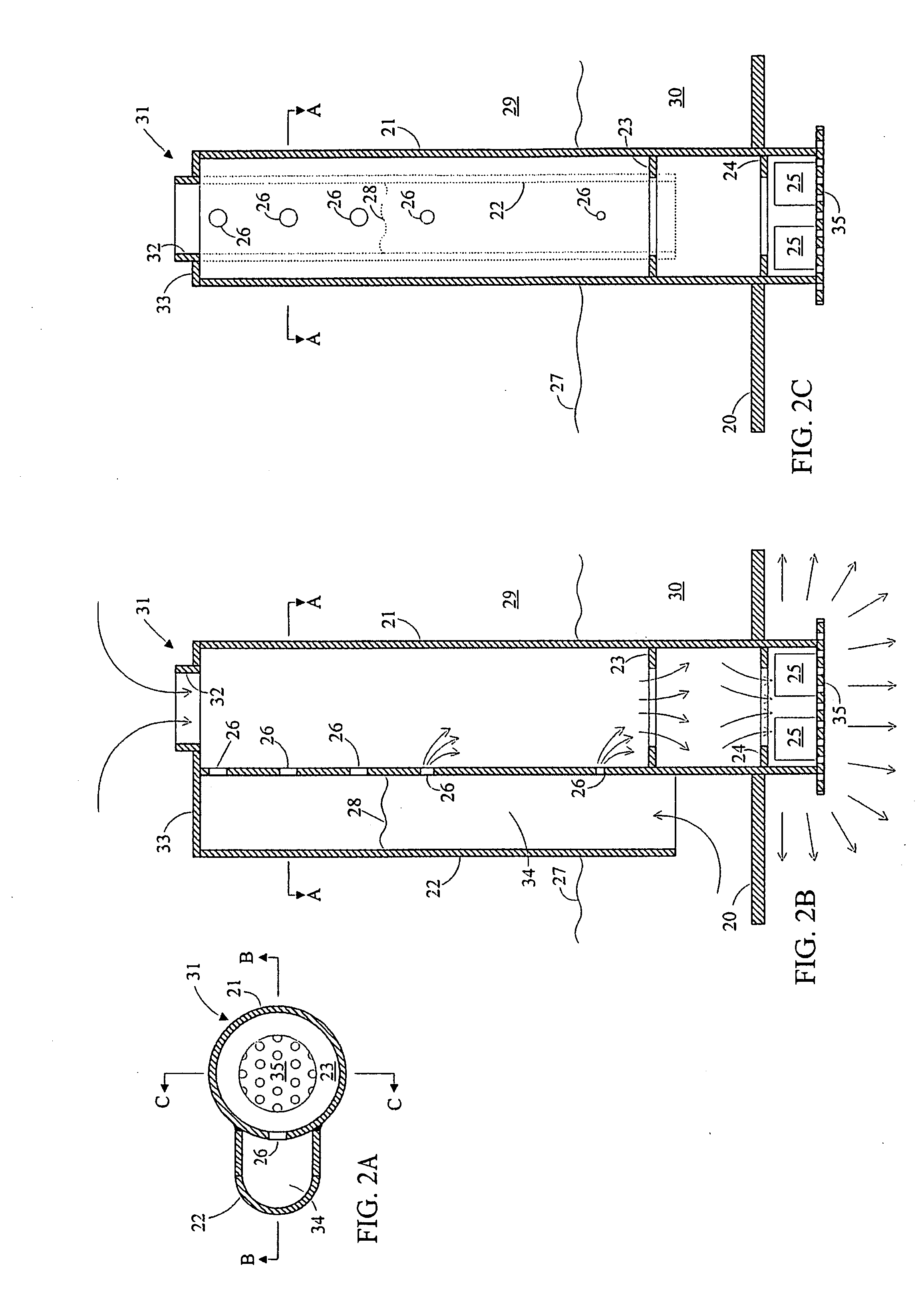
[0054] The majority of the vapor flows through the upper and open end of the downcomer and thereby generates a pressure drop due to friction and due to acceleration. This pressure drop is utilized to lift the liquid up into the liquid conduit through the liquid inlet. The liquid level in the liquid conduit is above some or all of the liquid openings, and liquid therefore flows through the liquid openings and into the downcomer where it is mixed with the downward flowing vapor. The two-phase mixture flows down through the downcomer and passes through the means for improving the liquid spread before it exits the downcomer.
[0055] The distribution tray has significantly improved distribution performance in terms of keeping close to identical liquid and vapor flow through all distribution units on the tray regardless of variations in liquid depth or vapor inlet pressure across the tray plate for a large range of both liquid and vapor flow rates. Due to the initial upward flow direction of the liquid in the liquid conduit, scale and particles tend to settle out upstream from the liquid openings. Therefore the distributor is less susceptible to fouling and plugging than a conventional chimney tray. The distribution unit, consisting of the downcomer and the liquid conduit, is very compact and the distribution units only occupy a small fraction of the tray area. Therefore the resistance to liquid flow across the tray is low, and the amounts of liquid by-passing the liquid openings through the vapor inlets are much lower than for a conventional chimney tray.

Problems solved by technology

The majority of the vapor flows through the upper and open end of the downcomer and thereby generates a pressure drop due to friction and due to acceleration.

Method used


Image

  • Distribution device for two-phase concurrent downflow vessels
  • Distribution device for two-phase concurrent downflow vessels
  • Distribution device for two-phase concurrent downflow vessels

Examples


Embodiment Construction

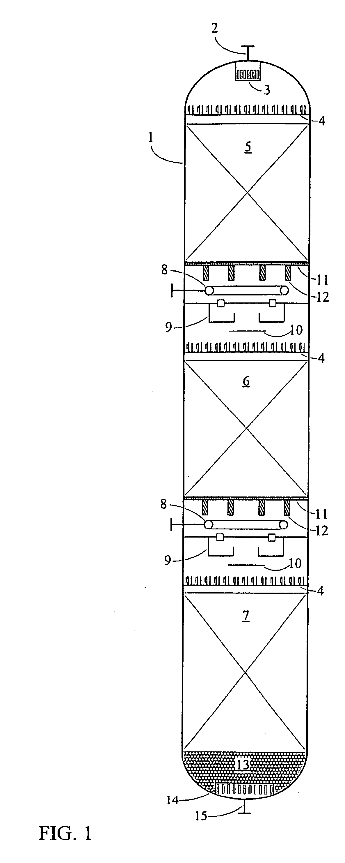
[0068] In commercial hydroprocessing reactors, the two-phase mixture of reactants flows concurrently downward through a fixed bed of solid catalyst particles. The ideal flow pattern in such a reactor is plug flow where liquid flows downward with the same velocity (based on empty reactor) at all points of the reactor cross-section. In the ideal plug flow case the same is true for the vapor phase: The vapor flows downward with identical velocity (based on an empty reactor) at all points of the reactor cross-section.

[0069] In commercial reactors plug flow is never achieved due to non-ideal distribution trays, uneven catalyst loading and / or the presence of deposits in the void space between the catalyst particles. Therefore, in some areas of the catalyst bed, the liquid flow velocity is higher than average, and the vapor velocity is lower than average. Due to the high heat capacity of the liquid relative to the vapor, the temperature rise in ° C. per meter of flow path is low in these ...


PUM

PropertyMeasurementUnit
diameteraaaaaaaaaa
diameteraaaaaaaaaa
pressureaaaaaaaaaa

Abstract

A distribution tray for distribution of vapor and liquid across a vessel has a plurality of downcomers extending above the tray and having open upper and lower ends. A liquid conduit for each downcomer has an inlet, a section for upward liquid flow, and openings in fluid communication with the downcomer. A reduced flow area section and a device for improved liquid spread may be used at the outlet of the downcomer. During operation, vapor enters the upper downcomer end. Liquid collected on the tray flows through the inlet, upward through the conduit, and through the openings into the downcomer, where the liquid is mixed with downwardly-flowing vapor. The two-phase stream passes the reduced flow area section with increased velocity for improved dispersion of the liquid before the stream flows through the device for improved liquid spread, and then exits through the lower end of the downcomer.

Description

CROSS-REFERENCE TO RELATED APPLICATION [0001] This application claims the benefit, under 35 U.S.C. §119(e), of co-pending provisional application no. 60 / 645,914, filed Jan. 21, 2005, the disclosure of which is incorporated herein by reference.FEDERALLY SPONSORED RESEARCH OR DEVELOPMENT [0002] Not Applicable BACKGROUND OF THE INVENTION [0003] The invention relates to a device for distributing vapor and liquid uniformly over the cross section of a vessel with two-phase concurrent downflow. The invention is suited for, but not limited to, the application of distributing hydrogen-rich treatgas and hydrocarbon liquid to the catalyst bed(s) in a hydroprocessing reactor, such as a hydrotreating or hydrocracking reactor. [0004] A large number of distribution tray designs for two-phase concurrent downflow vessels have been described in literature and patents. The majority of these designs belong to one of the two categories given below: [0005] Chimney Type of Distribution Trays: [0006] These...

Claims


Application Information

Patent Timeline
Patent Type & Authority Applications(United States)
IPC IPC(8): B01F3/04
CPCB01D3/20B01D3/205B01D3/26B01J8/0453B01J8/0492
Inventor MULLER, MORTEN
Owner MORTEN MULLER LTD APS
Why Eureka
Try Eureka