Fluid processing device comprising surface tension controlled valve

a technology of fluid processing device and valve, which is applied in the direction of nucleotide library, laboratory glassware, library creation, etc., can solve the problem that the flow of biological liquid cannot be resistant to the flow of biological liquid, and achieve the effect of reducing the resistance of the insulating layer

Inactive Publication Date: 2006-07-27
APPL BIOSYSTEMS INC
View PDF16 Cites 46 Cited by
  • Summary
  • Abstract
  • Description
  • Claims
  • Application Information

AI Technical Summary

Benefits of technology

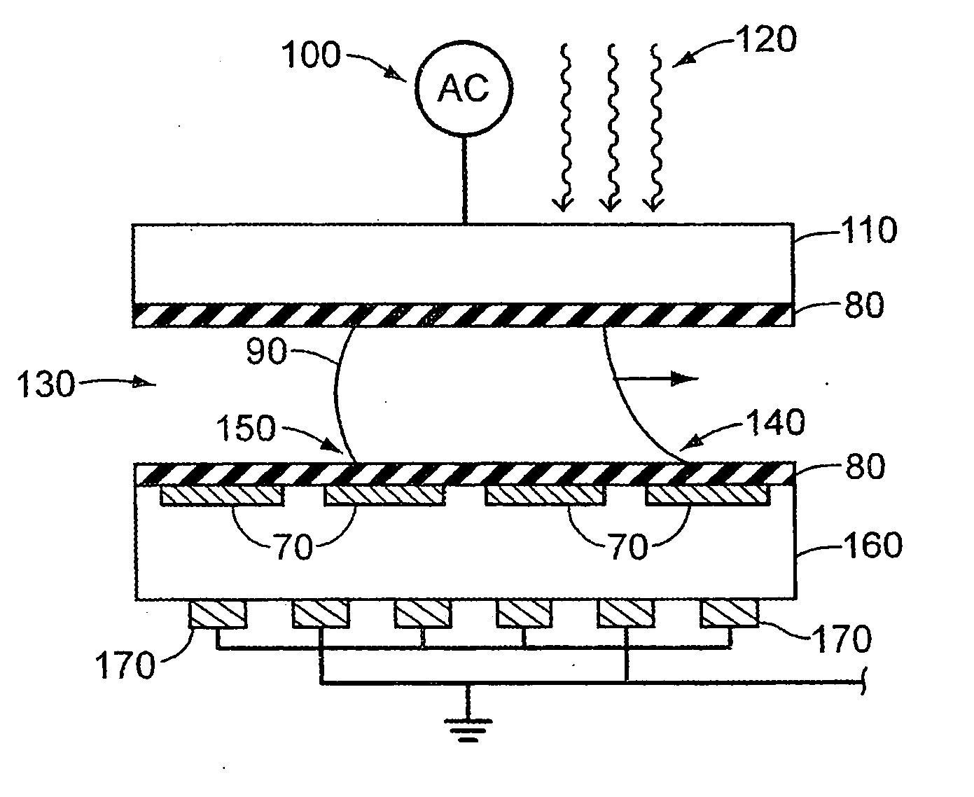
[0005] According to various embodiments, a device for biological fluid handling is provided that can comprise a valve configured for light activation. The device can comprise a channel connected to an internal volume. The internal volume can be bound by an insulating layer resistant to the flow of the biological liquid, wherein the channel can be non-resistant to the flow of the biological liquid. A photoconductive material can be coupled to the insulating layer. An electrode can be coupled to the photoconductive material and configured to electrically couple with the insulating layer through the photoconductive material. A power source can be electrically coupled to the electrode. The power source can be configured to provide an electrical potential difference between the photoconductive material and the biological fluid. A light source can be adapted to activate the photoconductive material thereby providing the electrical potential difference between the insulating layer and the biological fluid. The electrical potential difference can be configured to reduce the resistance of the insulating layer to the flow of the biological liquid.

Problems solved by technology

One of the challenges encountered in fluid processing devices, particularly devices designed for high throughput operations, is how to effectively control fluid flow.
The means for providing the biological fluid can be non-resistant to the flow of the biological liquid.

Method used


Image

  • Fluid processing device comprising surface tension controlled valve
  • Fluid processing device comprising surface tension controlled valve
  • Fluid processing device comprising surface tension controlled valve

Examples


Embodiment Construction

[0028] Reference will now be made to various exemplary embodiments, examples of which are illustrated in the accompanying drawings. Wherever possible, the same reference numbers are used in the drawings and the description to refer to the same or like parts.

[0029] For the purposes of this specification and appended claims, unless otherwise indicated, all numbers expressing quantities, percentages or proportions, and other numerical values used in the specification and claims, are to be understood as being modified in all instances by the term “about.” Accordingly, unless indicated to the contrary, the numerical parameters set forth in the following specification and attached claims are approximations that may vary depending upon the desired properties sought to be obtained by the present invention. At the very least each numerical parameter should at least be construed in light of the number of reported significant digits and by applying ordinary rounding techniques.

[0030] Notwith...


PUM


Abstract

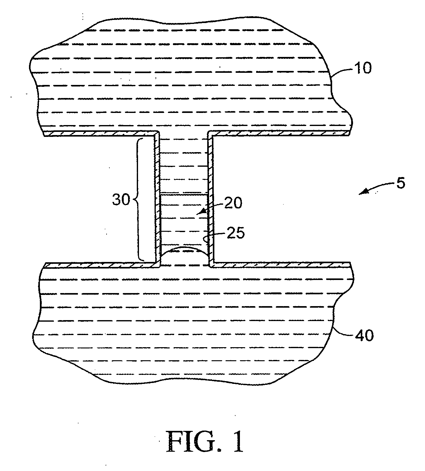
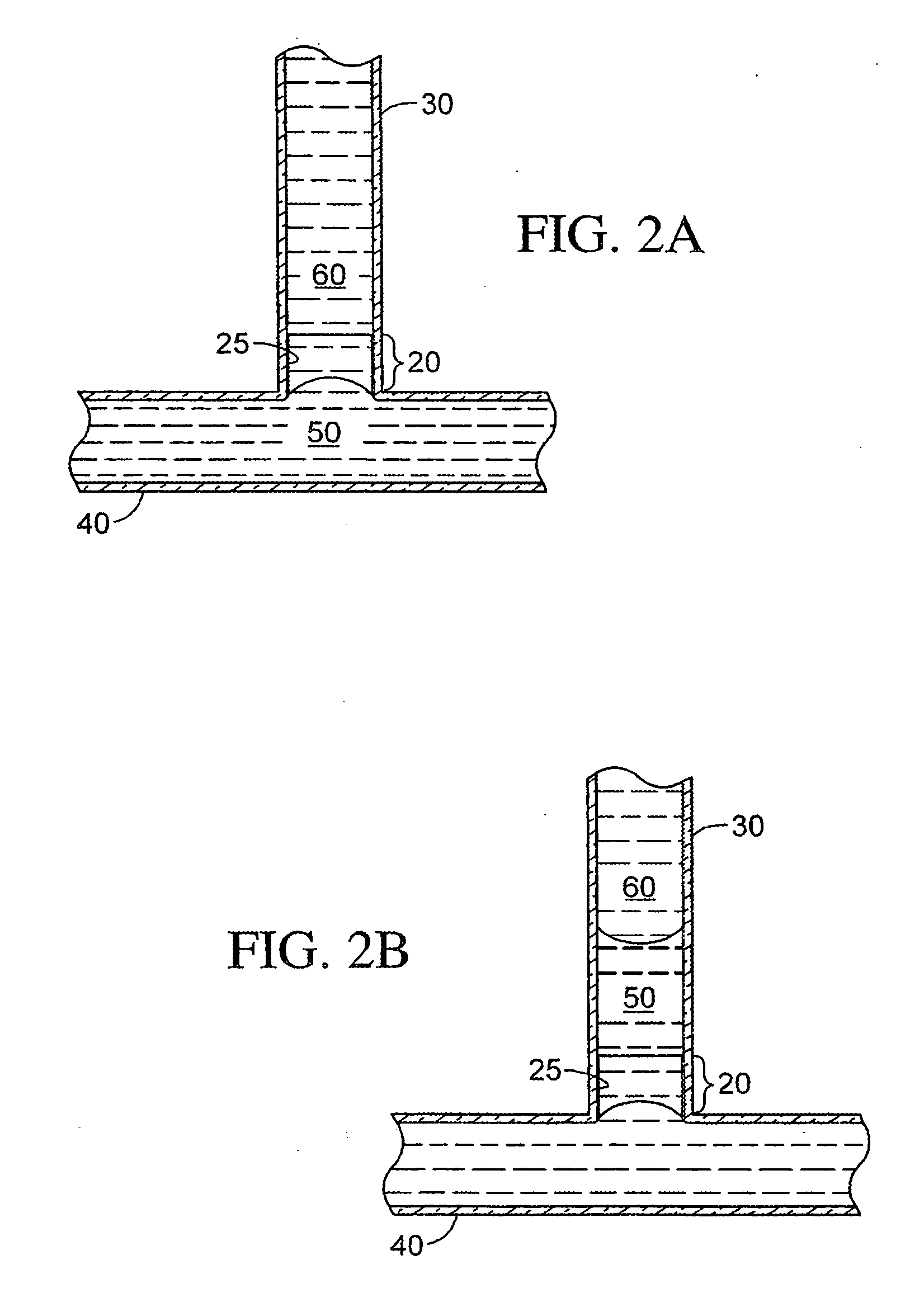
A fluid processing device adapted to produce different oligomers in a plurality of respective reaction sites and methods of using the same are provided. The fluid processing device can comprise a first manifold for delivering reactants to the plurality of reaction sites, and a second manifold for removing waste from, and optionally delivering wash fluid to, the plurality of reaction sites. Surface tension controlled valves can be disposed in fluid communication with the first manifold, the second manifold, or both, and can selectively allow reactants and / or fluids into the reaction sites. A method of making oligonucleotides is also provided.

Description

CROSS-REFERENCE TO RELATED APPLICATIONS [0001] This application is a continuation-in-part of U.S. patent application Ser. No. 11 / 092,180 filed on Mar. 29, 2005, and claims the benefit under 35 U.S.C. § 119(e) of Provisional Application No. 60 / 642,828 filed on Jan. 11, 2005, each of which is incorporated herein by reference in its entirety.FIELD [0002] The present teachings relate to valves in fluid processing devices, and methods for using the same. INTRODUCTION [0003] One of the challenges encountered in fluid processing devices, particularly devices designed for high throughput operations, is how to effectively control fluid flow. A need exists to individually and independently control fluid flow in thousands of micro-channels without resorting to the fabrication of sophisticated valving systems that can make microfluidic devices very expensive. SUMMARY [0004] According to various embodiments, a device and method for controlling fluid flow in a microfluidic system is provided. In ...

Claims


Application Information

Patent Timeline
Patent Type & Authority Applications(United States)
IPC IPC(8): B01J19/00
CPCB01J19/0046Y10T436/115831B01J2219/00369B01J2219/00389B01J2219/00439B01J2219/00441B01J2219/00448B01J2219/0045B01J2219/00675B01J2219/00695B01J2219/00722B01L3/502738B01L3/502784B01L3/502792B01L2200/0605B01L2300/0816B01L2300/0864B01L2400/0406B01L2400/0409B01L2400/0427B01L2400/0448B01L2400/0487B01L2400/0688B82Y30/00C40B40/06C40B50/14C40B60/14B01L7/52F15D1/00Y10T436/2575Y10T436/12B01J2219/00367Y10T137/0391Y10T137/2224Y10T137/206B01L3/50273B01L2200/10B01L2300/168B01L2400/0415B01L2400/06F15D1/06
Inventor ERMAKOV, SERGEY V.
Owner APPL BIOSYSTEMS INC
Why Eureka
Try Eureka