Optical recording medium

a technology of optical recording medium and optical recording medium, which is applied in the field of optical recording medium, can solve the problems of inability to reproduce data from the optical recording medium, inability to shorten the wavelength of the laser beam used in reproducing data, and inability to achieve the effect of increasing the numerical aperture na of the object lens,

Inactive Publication Date: 2006-07-27
TDK CORPARATION
View PDF8 Cites 8 Cited by
  • Summary
  • Abstract
  • Description
  • Claims
  • Application Information

AI Technical Summary

Benefits of technology

[0108] Hereinafter, examples will be described in order to make the effects of the invention be obvious.

Problems solved by technology

In an optical recording medium, if the length of a recording mark recorded on the optical recording medium and the length between the adjacent recording marks become less than the resolution limit, it is impossible to reproduce data from the optical recording medium.
Therefore, the length of the recording mark and blank region which can be formed when data is recorded on the optical recording medium is inevitably limited.
However, there is a limitation in shortening the wavelength λ of a laser beam used in reproducing data or increasing the numerical apertures NA of an object lens.
Further, there is a limitation in increasing the recording volume of the optical recoding medium by reducing the resolution limit.
Therefore, in the optical recoding medium disclosed in the document, when the data recorded in the optical recording medium is reproduced over a plurality of times, the signal characteristics of the reproduced signals are degraded so that the data cannot be reproduced stably.

Method used


Image

  • Optical recording medium
  • Optical recording medium
  • Optical recording medium

Examples


example 1

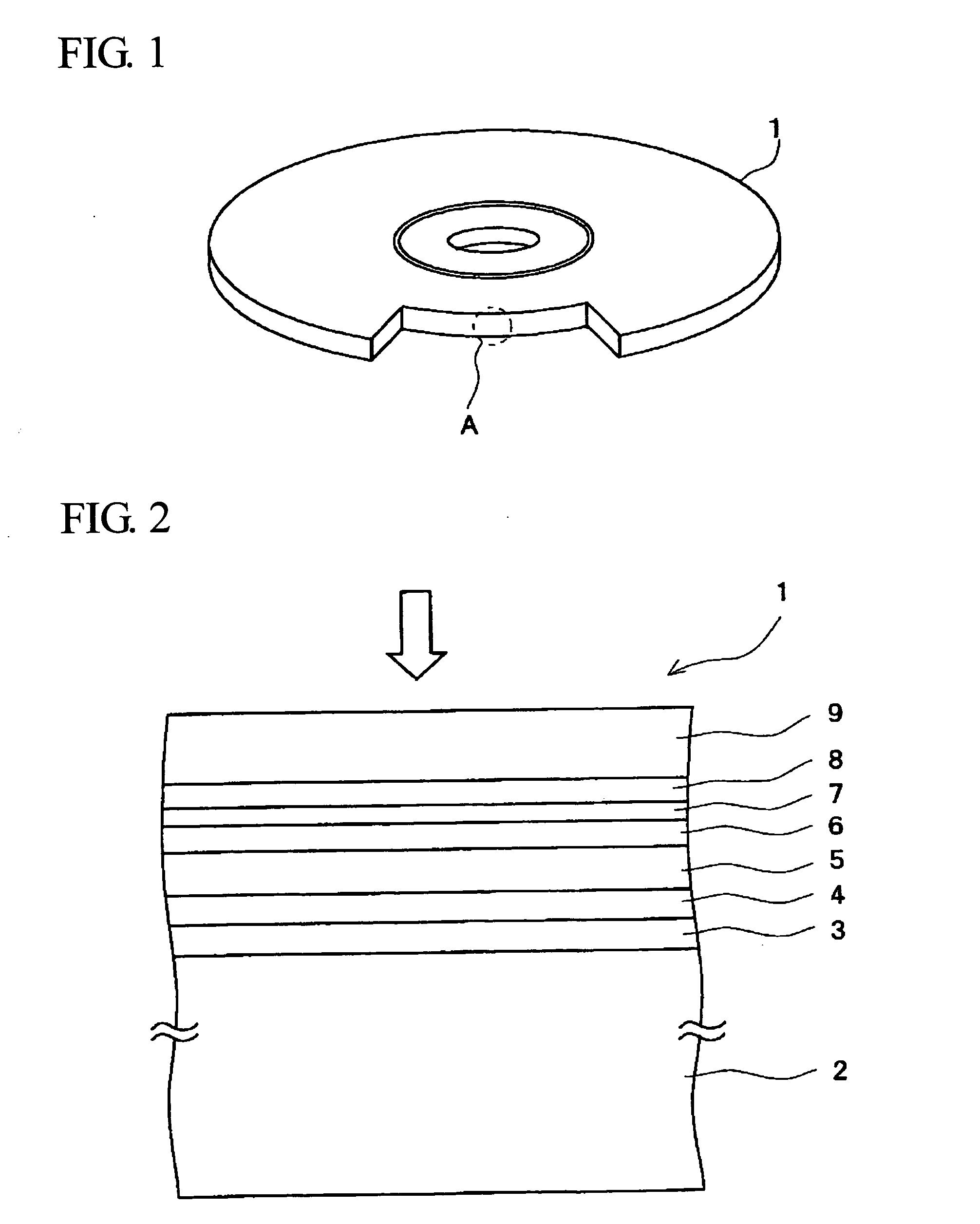
[0109] A polycarbonate substrate with a thickness of 1 mm and a diameter of 120 mm is set in a sputtering device to form a reflective layer with a thickness of 20 nm on the polycarbonate substrate using an alloy target of Ag, Pd, and Cu by a sputtering method.

[0110] Next, using a mixture target of ZnS and SiO2, the third dielectric layer having a thickness of 120 nm is formed on a surface of the reflective layer. As the mixture target of ZnS and SiO2, a target of which a molar ratio of ZnS:SiO2 is expressed by 80:20 is used

[0111] Next, using an alloy with a composition of Sb75Te25 as a target, the light absorbing layer having a thickness of 20 nm is formed on the surface of the third dielectric layer by a sputtering method.

[0112] Next, using a mixture target of ZnS and SiO2, the second dielectric layer having a thickness of 75 nm is formed on the surface of the light absorbing layer by a sputtering method. As the mixture target of ZnS and SiO2, a target of which a molar ratio of ...


PUM

PropertyMeasurementUnit
reflectanceaaaaaaaaaa
thicknessaaaaaaaaaa
decomposition temperatureaaaaaaaaaa

Abstract

An optical recording medium includes a laminated body in which at least a dielectric layer 6 is interposed between a recording layer 7 and a light absorbing layer 5, the optical recording medium being constructed so that data recorded by a recording mark train including recording marks whose lengths are less than the resolution limit are reproduced. The optical recording medium has reflectance of 20 to 80% and a laser beam is irradiated at a power density of 5.6×10⁸ to 1.2×10¹⁰ W / m2 to reproduce the recorded data.

Description

BACKGROUND OF THE INVENTION [0001] The present invention relates to an optical recording medium, and more specifically, to an optical recording medium in which data recorded by a recording mark train can be stably reproduced over a plurality of times, the recording mark train including at least one of a recording mark and a blank region, whose length is less than the resolution limit. [0002] Conventionally, as a recoding medium for recording digital data, an optical recording medium which is represented by CD or DVD has been widely used. Recently, however, the development of an optical recording medium having a large capacity and a high data transfer rate is being actively performed. In such an optical recoding medium, the wavelength λ of a laser beam used in recording and reproducing data is shortened, and the beam spot diameter of the laser beam becomes smaller by increasing the numerical apertures NA of an object lens, thereby increasing the recoding capacity of the optical recod...

Claims


Application Information

Patent Timeline
Patent Type & Authority Applications(United States)
IPC IPC(8): B32B3/02G11B7/24G11B7/24035G11B7/243G11B7/2433G11B7/254G11B7/257
CPCG11B7/00452G11B7/243G11B2007/2432G11B7/241G11B7/257
Inventor KOBAYASHI, TATSUHIROKIKUKAWA, TAKASHIFUKUZAWA, NARUTOSHI
Owner TDK CORPARATION
Why Eureka
Try Eureka