Illuminant distribution evaluation method, optical member manufacturing method, illumination optical device, exposure apparatus, and exposure method

a technology of illumination distribution and manufacturing method, applied in the direction of optical apparatus testing, optical radiation measurement, instruments, etc., can solve the problems of difficult to obtain a surface shape of a higher quality, yield rate is considerably lower than that of a fly's-eye lens, and it is difficult to process all of the micro refracting surfaces with a very high precision of several tens of nm

Inactive Publication Date: 2006-07-27
NIKON CORP
View PDF5 Cites 8 Cited by
  • Summary
  • Abstract
  • Description
  • Claims
  • Application Information

AI Technical Summary

Benefits of technology

[0014] It is an aspect of the present invention, contrived in view of the above-mentioned problems, to provide an evaluation method which can

Problems solved by technology

However, in a micro fly's-eye lens, since all of the micro refracting surfaces should be manufactured simultaneously by etching, which is difficult to obtain a surface shape of a higher quality than the polishing, the yield rate becomes considerably lower than that of a fly's-eye lens.
However, in a micro fly's-eye lens with all of the micro refracting surfaces being simultaneously manufacture

Method used


Image

  • Illuminant distribution evaluation method, optical member manufacturing method, illumination optical device, exposure apparatus, and exposure method
  • Illuminant distribution evaluation method, optical member manufacturing method, illumination optical device, exposure apparatus, and exposure method
  • Illuminant distribution evaluation method, optical member manufacturing method, illumination optical device, exposure apparatus, and exposure method

Examples


Embodiment Construction

[0068] Embodiments of the present invention will be described, referring to the accompanying drawings.

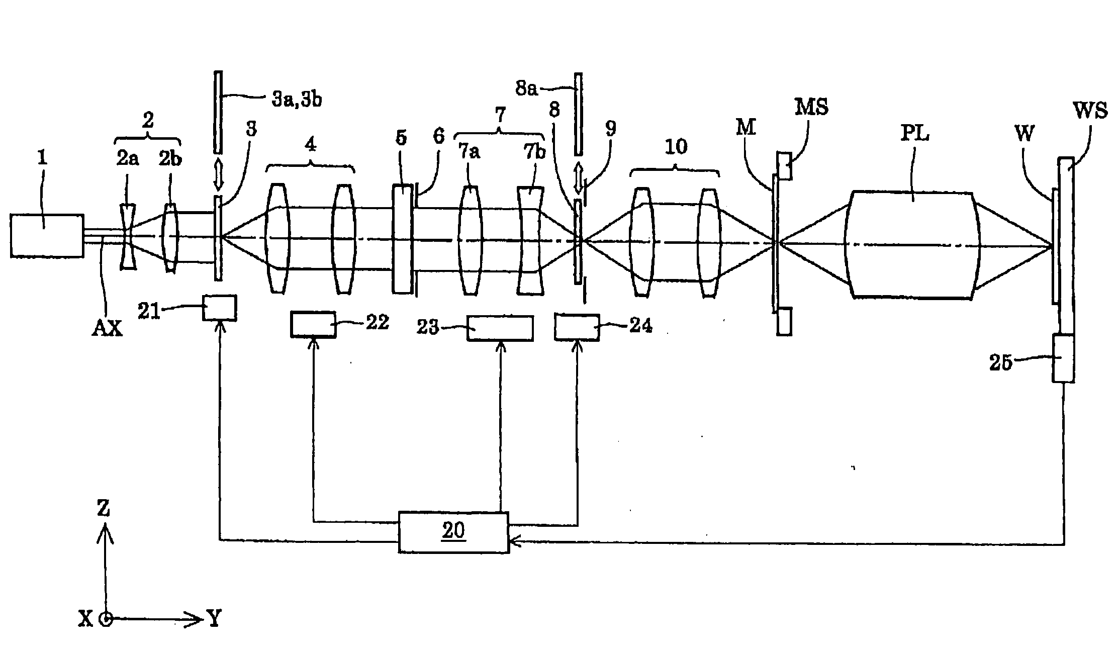
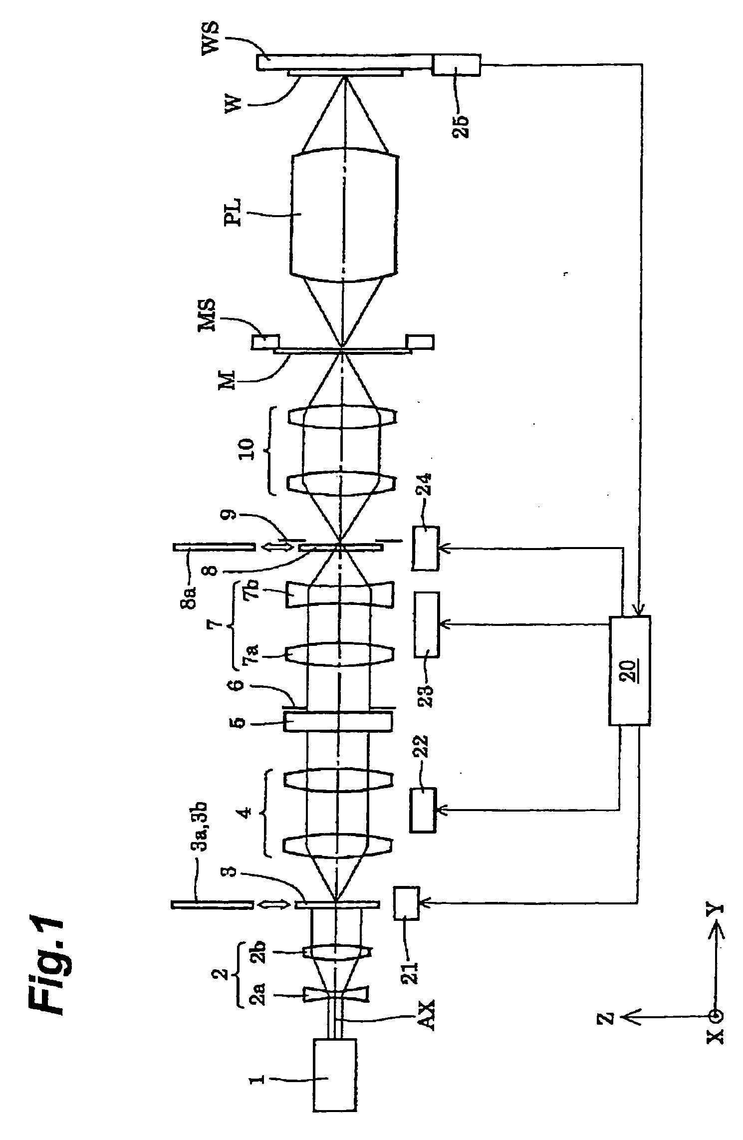
[0069]FIG. 1 is a schematic view illustrating an arrangement of an exposure apparatus comprising an illumination optical apparatus according to an embodiment of the present invention. In FIG. 1, the Y-axis is taken along the normal direction of a wafer W which is a photosensitive substrate, and X- and Z-axes are respectively taken along two directions orthogonal to each other within a surface which is parallel to the wafer W. Note that, in FIG. 1, the illumination optical apparatus is arranged to perform a normal circular illumination.

[0070] The exposure apparatus of the present embodiment comprises a laser source 1 for providing exposure light (illuminating light). As the laser source 1, a KrF excimer laser source supplying light with 248 nm wavelength, or an ArF excimer laser source supplying light with 193 nm wavelength may be used, for example. The approximately parallel light...


PUM


Abstract

There is disclosed an evaluation method for evaluating a one-dimensional illumination distribution using polynomials, the method comprising steps of: setting up, as the polynomials, one-dimensional power polynomials which are orthogonal in a closed interval; and approximating the one-dimensional illumination distribution with the power polynomials to obtain the coefficients of respective terms of the power polynomials.

Description

CROSS-REFERENCE TO RELATED APPLICATIONS [0001] This is a continuation-in-part application of application serial no. PCT / JP2004 / 011131 filed on Aug. 4, 2004, now pending, and incorporated by reference in its entirety.BACKGROUND OF THE INVENTION [0002] 1. Field of the Invention [0003] The present invention relates to a method of evaluating illumination distribution, a manufacturing method of an optical member, an illumination optical device, an exposure apparatus, and an exposure method, and particularly to manufacturing of a micro fly's-eye lens used in an illumination optical apparatus of an exposure apparatus for manufacturing micro devices, e.g. semiconductor devices, imaging devices, liquid crystal display devices, thin film magnetic heads or the like, through lithography processing. [0004] 2. Related Background Art [0005] In such a typical exposure apparatus, a light beam emitted from a light source enters a fly's-eye lens to form, on its back focal plane, a secondary light sour...

Claims


Application Information

Patent Timeline
IPC IPC(8): G03C5/00G01J1/02G01M11/02G02B3/00G03F7/20H01L21/027
CPCG01M11/0207G03F7/70075
Inventor TOYODA, MITSUNORIKITA, NAONORI
Owner NIKON CORP
Why Eureka
Try Eureka