Auto Motion: Robot Guidance for Manufacturing

a technology of robot guidance and manufacturing, applied in the field of robot automation, can solve the problems of robots not being able to match the hand-eye coordination of people and their ability, unable to meet the needs of mass production automobile companies, and unable to meet the operation of moving conveyors, etc., to achieve the effect of reducing production costs, reducing production efficiency, and reducing production efficiency

Inactive Publication Date: 2006-07-27
READ DALE
View PDF0 Cites 141 Cited by
  • Summary
  • Abstract
  • Description
  • Claims
  • Application Information

AI Technical Summary

Benefits of technology

[0010] According to one aspect of the present invention, there is provided a robot manufacturing facility including at least one robot for acting on a workpiece or intermediate product of a pre-calculated shape and dimensions at a pre-calculated position and orientation relative to a reference frame, the robot including a body or base structure, at least one member movable with respect to said body or base structure for acting on such workpiece or intermediate product, means for effecting such movement and sensing means for sensing the position of said member, the last noted means including means for sensing the position of the workpiece or intermediate product relative to the robot or to said member thereof and means for controlling the movement of said member relative to said body or base structure according to a predetermined program, modified in accordance with signals from said sensing means, whereby the robot is able to compensate for departures from said pre-calculated values of the position and orientation and / or shape and / or dimensions of the workpiece or intermediate product.

Problems solved by technology

However, robots have not so far been able to match the hand-eye co-ordination of people and their ability to make instant decisions based on visually observed circumstances.
Operations on moving conveyors, the foundation of mass production automobile companies, are, however, still very labour intensive.
Robots that follow a predefined path, however, would often miss their target and produce considerable amounts of scrap product.
High investment in tooling is thus a pre-requisite to a robot cell which adversely affects the payback analysis, takes up large areas of plant space and creates more equipment to maintain.

Method used


Image

  • Auto Motion: Robot Guidance for Manufacturing
  • Auto Motion: Robot Guidance for Manufacturing
  • Auto Motion: Robot Guidance for Manufacturing

Examples


examples

1. Robot Glazing (Pictures in FIG. 2)

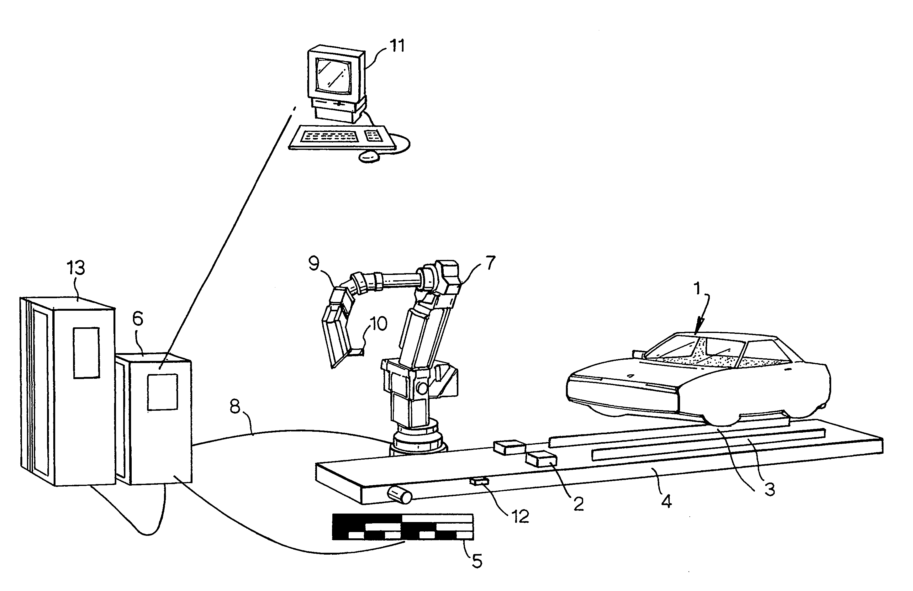
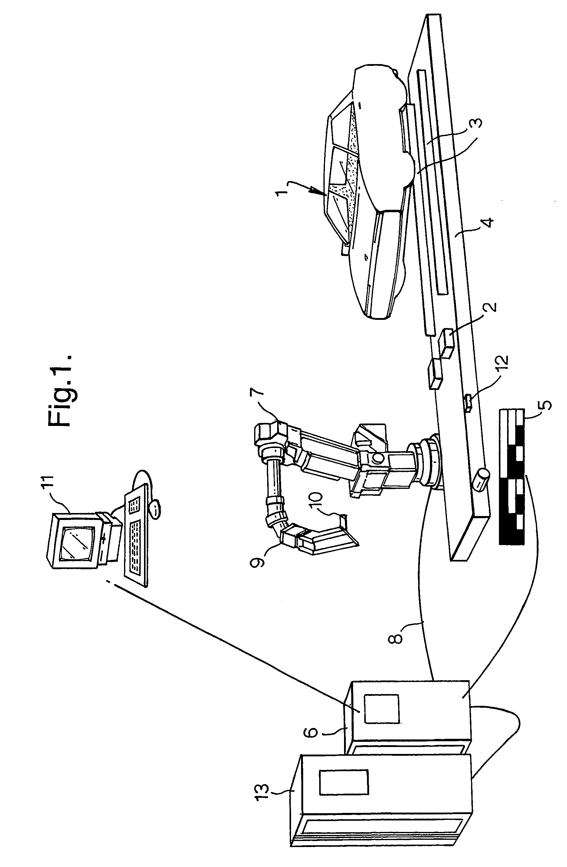
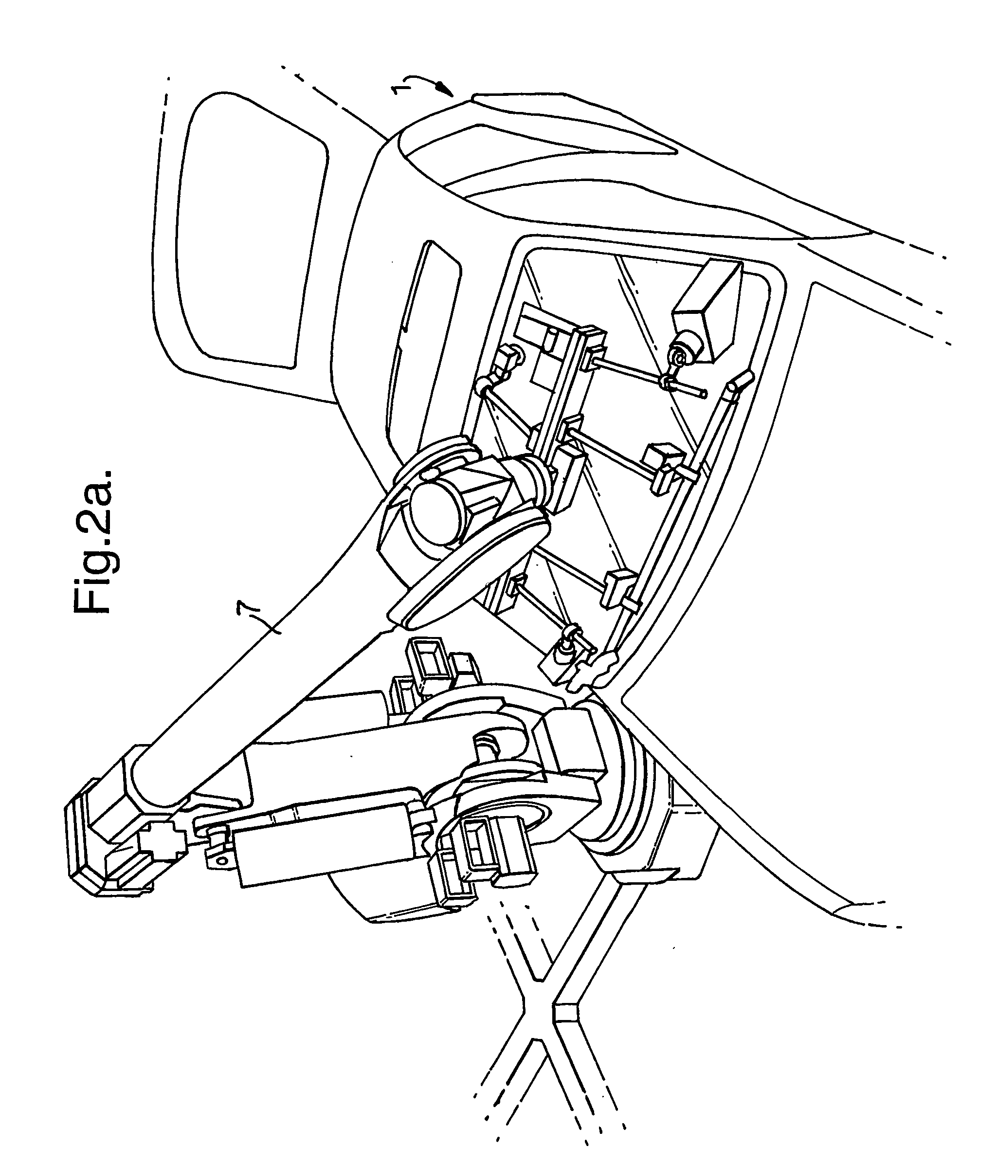
[0067] The glazing cell illustrated is a prime candidate for application of the principle of ‘on-the-fly’ component insertion in accordance with the invention. The cell illustrated is designed to use a dynamic glazing principle where the car body travels on its original skid and conveyor system through the glazing cell without stopping. The robot responsible for decking the front windscreen has to follow the moving car body through the cell as shown in FIG. 2(a). The process described here is similar to ‘on the fly’ above but with a focus on windscreen glass. In this embodiment, the robot effector includes a vacuum suction pad to hold the windscreen without damaging the latter.

[0068] The tracking function for the robot is achieved by connecting a digital encoder to the conveyor drive to measure the conveyor position at any time. This robot interprets the signal and uses it to synchronise itself with the conveyor. This synchronising routine is ...


PUM


Abstract

A robot manufacturing facility, for example for use in automobile manufacture, includes at least one robot for acting on a workpiece or intermediate product of a pre-calculated shape and dimensions at a pre-calculated position and orientation relative to a reference frame. The robot includes a body or base structure, at least one end effector movable with respect to the body or base structure for acting on workpieces, means for moving the end effector and sensing means for sensing the position of the each effector. The sensing means preferably includes a laser light source carried by the robot and means for detecting laser light, from said source, reflected from the workpiece. The movement of the end effector is controlled according to a predetermined program, modified in accordance with signals from the sending means, so that the robot is able to compensate for departures from pre-calculated values of the position and orientation and / or shape and / or dimensions of the workpiece.

Description

TECHNICAL FIELD [0001] THE PRESENT INVENTION relates to robot automation, particularly in the customisation of robot actions to the immediate situation presented, whether dimensional variation in the target to be operated on, or motion on a conveyor. BACKGROUND OF THE INVENTION [0002] Robot automation has long been available for replacing manual operators in highly repetitive tasks. A robot's reach, payload capacity, repeatability and ability to work continuously and in hazardous areas are far superior to that of a human. However, robots have not so far been able to match the hand-eye co-ordination of people and their ability to make instant decisions based on visually observed circumstances. [0003] In the automotive industry, robot automation has therefore thrived in body construction where the panels are clamped in a known position, and where simple sensing (through proximity or photoelectric sensors) can determine which of several defined programs must be run for that particular ...

Claims


Application Information

Patent Timeline
Patent Type & Authority Applications(United States)
IPC IPC(8): G06F19/00B23Q9/00B23Q17/24B25J9/16B25J9/18B62D65/02G05B19/401G05B19/402G05B19/418
CPCB23Q9/00B23Q17/24B25J9/1697B62D65/02G05B19/401G05B19/402G05B19/4182G05B2219/36404G05B2219/37288G05B2219/39102G05B2219/40613G05B2219/45025G05B2219/45064Y02P90/02
Inventor READ, DALE
Owner READ DALE
Why Eureka
Try Eureka