Etchant treatment processes for substrate surfaces and chamber surfaces

a technology of substrate surface and chamber surface, which is applied in the direction of cleaning process and apparatus, cleaning process using liquids, chemistry apparatus and processes, etc., can solve the problems of affecting the etching rate of substrate surface containing silicon-containing materials, and affecting the etching rate of substrate surface. , to achieve the effect of fast etching rate and low temperatur

Active Publication Date: 2006-08-03
APPLIED MATERIALS INC
View PDF99 Cites 81 Cited by
  • Summary
  • Abstract
  • Description
  • Claims
  • Application Information

AI Technical Summary

Benefits of technology

[0011] In another embodiment, a method for etching a silicon-containing surface is provided which includes removing silicon-containing material at a fast rate in order to form a recess in a source/drain (S/D) area on the substrate. In another example, a substrate is placed into a process chamber and heated to a temperature within a range from about 500° C. to about 800° C. While the substrate is heated, the silicon-containing surface contained thereo

Problems solved by technology

The deposition and removal steps as well as other process steps may cause the substrate surface containing a silicon-containing material to become rough and/or bare contaminants.
Also, particulates and other contaminants accumulate on the interior surfaces within a process chamber during the deposition and removal steps.
The particulates may eventually further contaminate the substrate surface.
Rough or contaminated substrate surfaces generally lead to poor quality interfaces which provide poor device performance and reliability.
Howev

Method used


Image

  • Etchant treatment processes for substrate surfaces and chamber surfaces
  • Etchant treatment processes for substrate surfaces and chamber surfaces
  • Etchant treatment processes for substrate surfaces and chamber surfaces

Examples


example 1

Pre-Clean Process Comparative without Silane

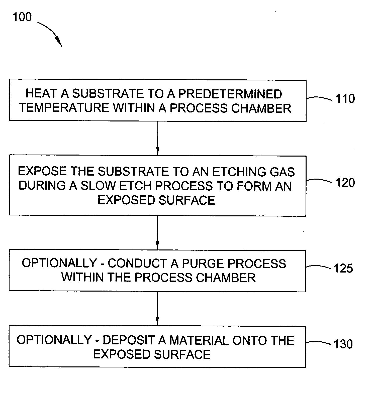
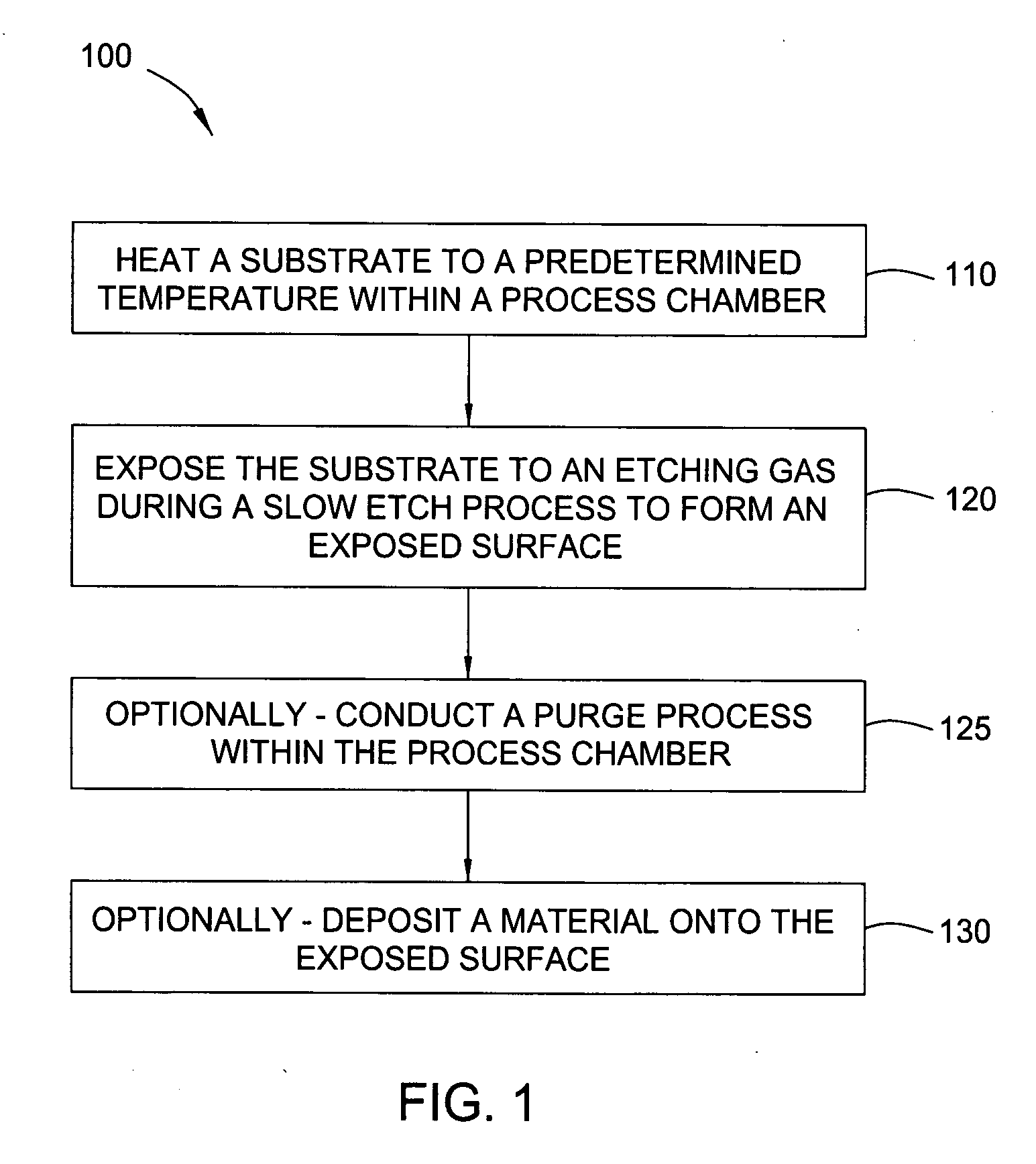
[0064] A substrate was exposed to an HF-last process to form a fluoride terminated surface. The substrate was placed in the process chamber and heated to about 600° C. while the pressure was maintained at about 20 Torr. The substrate was exposed to an etching gas containing N2 at a flow rate of about 20 slm and Cl2 at flow rate of about 120 sccm. The surface was etched at a rate of about 500 Å / min.

example 2

Pre-Clean Process with Silane

[0065] A substrate was exposed to an HF-last process to form a fluoride terminated surface. The substrate was placed in the process chamber and heated to about 600° C. while the pressure was maintained at about 20 Torr. The substrate was exposed to an etching gas containing N2 at a flow rate of about 20 slm, Cl2 at flow rate of about 20 sccm and SiH4 at a flow rate of about 50 sccm. The surface was etched at a rate of about 10 Å / min. Therefore, the addition of a silicon source, such as silane in Example 2, reduced the etch rate of the silicon-containing layer by about 50 times as compared to the etch rate in Example 1.

example 3

Smoothing Process Comparative without Silane

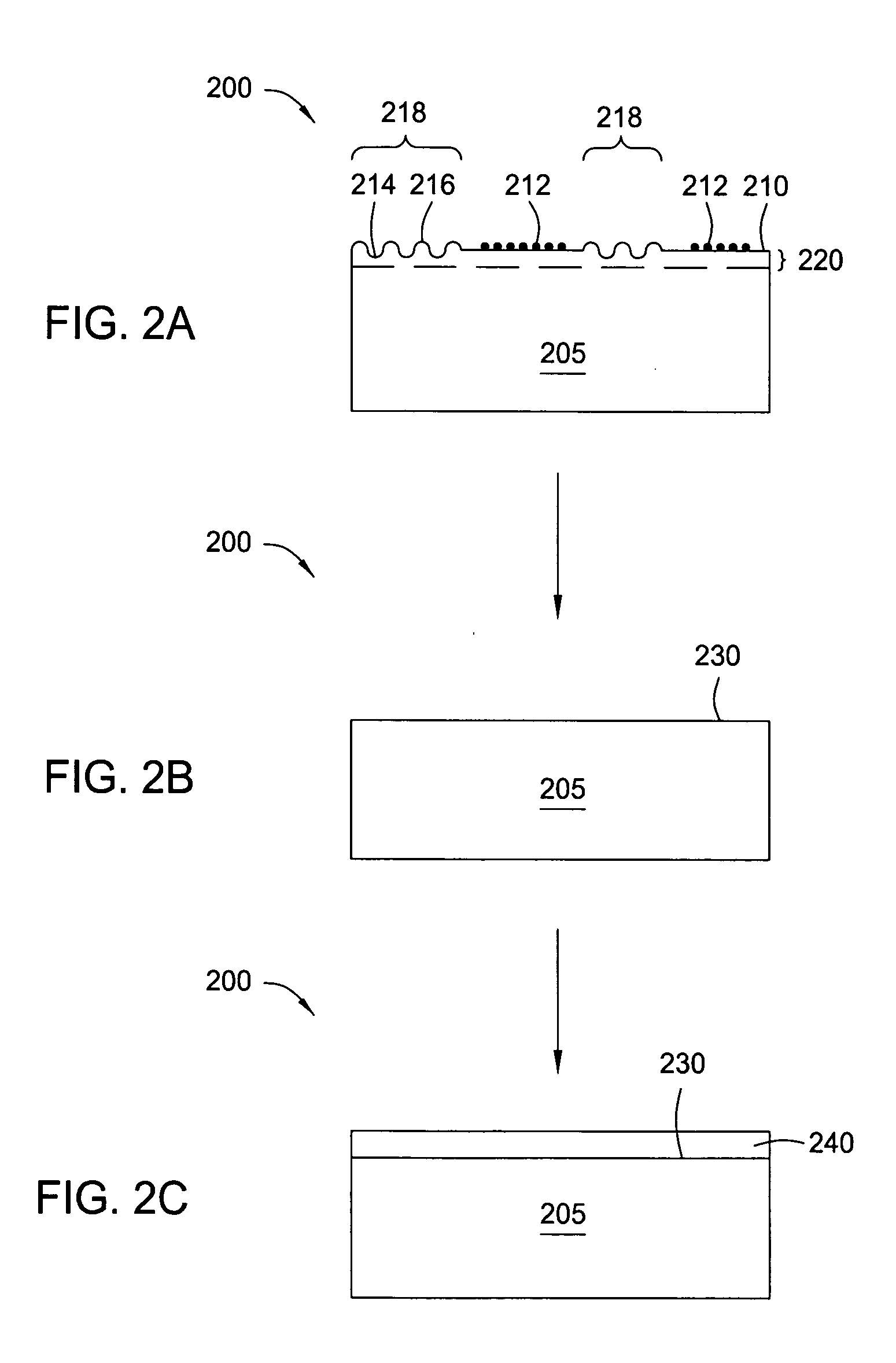
[0066] A substrate surface containing a silicon-containing layer was cleaved forming a surface with a roughness of about 5.5 nm root mean square (RMS). The substrate was placed in the process chamber and heated to about 650° C. while the pressure was maintained at about 200 Torr. The substrate was exposed to an etching gas containing N2 at a flow rate of about 20 slm and Cl2 at flow rate of about 20 sccm. The surface was etched at a rate of about 200 Å / min.


PUM

PropertyMeasurementUnit
Temperatureaaaaaaaaaa

Abstract

In one embodiment of the invention, a method for finishing or treating a silicon-containing surface is provided which includes removing contaminants and/or smoothing the surface contained on the surface by a slow etch process (e.g., about <100 Å/min). The silicon-containing surface is exposed to an etching gas that contains an etchant and a silicon source. Preferably, the etchant is chlorine gas so that a relatively low temperature (e.g., <800° C.) is used during the process. In another embodiment, a method for etching a silicon-containing surface during a fast etch process (e.g., about >100 Å/min) is provided which includes removing silicon-containing material to form a recess in a source/drain (S/D) area on the substrate. In another embodiment, a method for cleaning a process chamber is provided which includes exposing the interior surfaces with a chamber clean gas that contains an etchant and a silicon source. The chamber clean process limits the etching of quartz and metal surfaces within the process chamber.

Description

CROSS-REFERENCE TO RELATED APPLICATIONS [0001] This application is a continuation-in-part of co-pending U.S. Ser. No. 11 / 047,323 (APPM / 009793), filed Jan. 31, 2005, which is herein incorporated by reference.BACKGROUND OF THE INVENTION [0002] 1. Field of the Invention [0003] Embodiments of the invention generally relate to the field of electronic manufacturing processes and devices, more particular, to methods of etching and depositing silicon-containing materials while forming electronic devices. [0004] 2. Description of the Related Art [0005] Electronic devices such as semiconductor devices are fabricated by an assortment of steps including the deposition and removal of silicon-containing materials. The deposition and removal steps as well as other process steps may cause the substrate surface containing a silicon-containing material to become rough and / or bare contaminants. Also, particulates and other contaminants accumulate on the interior surfaces within a process chamber durin...

Claims


Application Information

Patent Timeline
IPC IPC(8): B44C1/22C03C25/68H01L21/311C03C15/00B08B6/00
CPCB08B7/0035H01L21/02019H01L21/02046H01L21/02057H01L21/3065H01L21/823425H01L21/823807H01L21/823814H01L21/02381H01L21/02532H01L21/0262H01L21/02658H01L21/02529
Inventor ZOJAJI, ALISAMOILOV, ARKADII V.
Owner APPLIED MATERIALS INC
Why Eureka
Try Eureka