
Method for air conditioning a motor vehicle

a technology for air conditioning and motor vehicles, applied in air humidification systems, heating types, lighting and heating apparatus, etc., can solve problems such as unfavorable window fogging, and achieve the effect of preventing the window fogging of motor vehicles

Active Publication Date: 2006-08-03
CHEMTRON RES
View PDF15 Cites 5 Cited by
  • Summary
  • Abstract
  • Description
  • Claims
  • Application Information

AI Technical Summary

Benefits of technology

[0005] The invention is based on the object of developing a method of the generic type in such a manner that fogging of the windows of the motor vehicle is prevented from the outset.
[0007] As a result of the humidity within the passenger compartment in relation to the passenger compartment temperature being recorded by measurement technology and of a heat source which is external to the refrigeration circuit being used, the heat source for heating the passenger compartment is started up when a threshold value for the humidity at a defined temperature is reached. At the same time, the mass flow of refrigerant through the evaporator is throttled to a sufficient extent for there to be virtually no introduction of heat into the passenger compartment via the evaporator. As a result, the condensate remains at the heat exchanger forming the evaporator, or the feed air to the passenger compartment is dried by condensation at the evaporator. The external heat source as it were functionally replaces the evaporator for heating the passenger compartment. Only when a defined temperature level has been reached in the passenger compartment is the external heat source decoupled and the throttling of the mass flow of refrigerant through the evaporator relieved. This creates air-conditioning in which the passenger compartment can be heated at low temperatures without fogging of the windows. The method according to the invention is particularly advantageous when CO2 is used as refrigerant, on account of the superior use qualities of CO2 compared to other refrigerants in heat pump mode, which derive from its physical properties at the given pressure level.

Problems solved by technology

However, the air flowing past the evaporator into the passenger compartment takes up some of the moisture which is present at the evaporator and transports it, inter alia, onto the windows of the motor vehicle, which for a certain period of time leads to undesirable fogging of the windows.

Method used


Image

  • Method for air conditioning a motor vehicle
  • Method for air conditioning a motor vehicle

Examples


Embodiment Construction

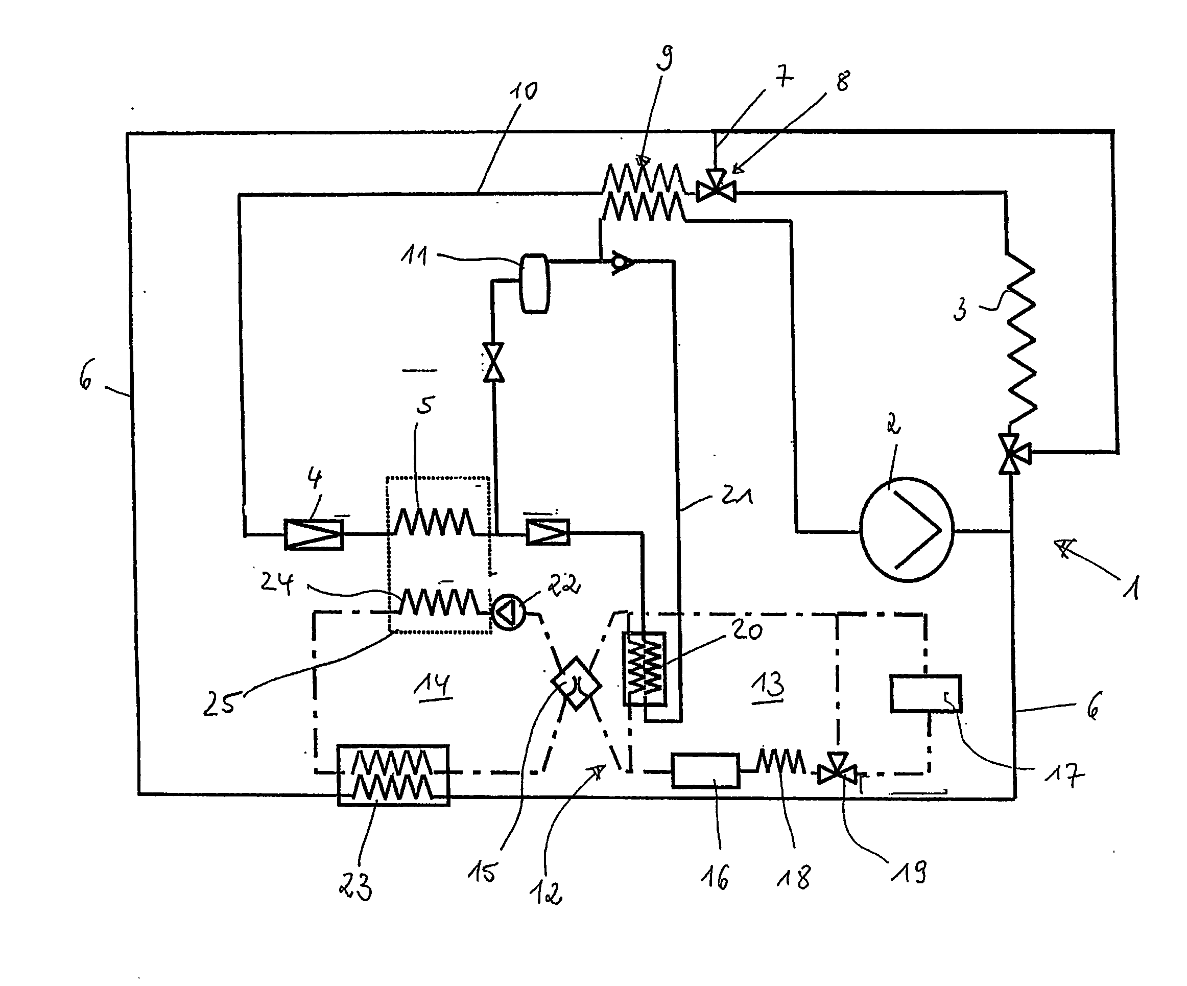
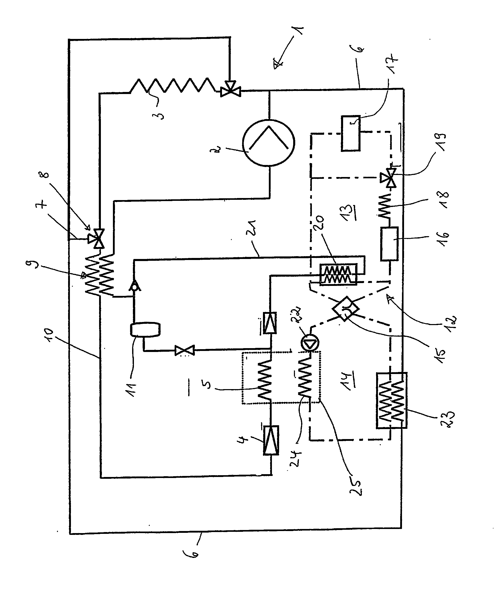
[0009] The FIGURE illustrates an air-conditioning circuit 1 of an air-conditioning system of a motor vehicle which can be used both to cool a passenger compartment of the motor vehicle and to heat the passenger compartment. The basic components of the circuit comprise a compressor 2, a condenser 3, a throttle valve 4 and an evaporator 5 used as passenger compartment heat exchanger. In heating mode, the circuit 1 is switched to heat pump operation, according to which the hot refrigerant—CO2—which has been compressed to a high pressure level by the compressor 2 is made to bypass the condenser 3 via a bypass line 6. The hot refrigerant then passes a branch line 7, which is connected to the bypass line 6 and has a 3 / 2-way valve 8, from which it flows through the heat flux section of a countercurrent heat exchanger 9 of a continuation line 10, releasing a small amount of its heat to the cool countercurrent. Furthermore, the refrigerant, which is still relatively hot, flows through the th...


PUM


Abstract

The invention relates to a method for air conditioning a motor vehicle, in which, in a heating mode, the passenger compartment of the motor vehicle is heated via a passenger compartment heat exchanger (5) through heat pump operation of a refrigerating circuit (1) comprising a compressor (2), a condenser (3), a throttle valve (4) and the passenger compartment heat exchanger (5), with the temperature in the passenger compartment being recorded by measurement technology. To prevent fogging of the windows of the motor vehicle from the outset, it is proposed that in addition the atmospheric humidity in the passenger compartment is recorded by measurement technology, and that when the temperature is in a predefined range and the atmospheric humidity reaches a defined threshold, the mass flow of refrigerant in the circuit is throttled upstream of the passenger compartment heat exchanger (5), in such a manner that the moisture contained in the air stream passing the passenger compartment heat exchanger (5) is at least substantially condensed at the passenger compartment heat exchanger (5), and the moisture which has already condensed at the heat exchanger (5) remains at the heat exchanger (5), and in that the passenger compartment is heated by a heat source which is outside the circuit (1) until the temperature in the passenger compartment exceeds an upper limit temperature of the predefined range.

Description

BACKGROUND OF THE INVENTION [0001] 1. Field of the Invention [0002] The invention relates to a method for air conditioning a motor vehicle in accordance with the preamble of patent claim 1. [0003] 2. Related Art of the Invention [0004] A method of the generic type is known from DE 36 35 353 A1, in which it is described that the air-conditioning system should be run in heat pump mode in order to rapidly heat a passenger compartment and to defrost frozen or fogged windows. In this case, the actual condenser of the air-conditioning circuit is bypassed downstream of the compressor via a bypass line, after which the heated cooling medium passes through the evaporator, which functions as a condenser and also has an air stream passed into the passenger compartment passing through it. The cooling medium which has cooled there then takes up heat from a third heat exchanger, which serves as an evaporator and has the coolant of the internal combustion engine flowing through it. During a cold s...

Claims


Application Information

Patent Timeline
Patent Type & Authority Applications(United States)
IPC IPC(8): F24D1/00B60H1/00F25B5/04F25B9/00F25B40/00
CPCB60H1/00785B60H1/00914B60H2001/00957F25B5/04F25B9/008F25B40/00F25B2309/061F25B2400/0403F25B2700/02
Inventor CAESAR, ROLANDGAERTNER, JANWERTENBACH, JURGEN
Owner CHEMTRON RES
Learn More