
Microelectronic cleaning agent(s) and method(s) of fabricating semiconductor device(s) using the same

a technology of microelectronic cleaning agent and semiconductor device, which is applied in the direction of detergent compounding agent, glass wing, inorganic non-surface active detergent composition, etc., can solve the problems of surface treatment agent coming into contact, current leakage increase inversely, and leakage current increas

Inactive Publication Date: 2006-08-03
SAMSUNG ELECTRONICS CO LTD
View PDF9 Cites 23 Cited by
  • Summary
  • Abstract
  • Description
  • Claims
  • Application Information

AI Technical Summary

Benefits of technology

[0019] According to another aspect of an example embodiment of the present invention, there is provided a method of fabricating a semiconductor device using one or more of the above-noted microelectronic cleaning agents. The method may include forming a dielectric layer on a semiconductor substrate, and forming a mask pattern on the semiconductor substrate and exposing the dielectric layer through the mask pattern to form exposed regions of the dielectric layer. Subsequently, the exposed dielectric layer may then be etched using a microelectronic cleaning agent. According to an example embodiment of the present invention, microelectronic cleaning agent may include

Problems solved by technology

However, with a thin silicon oxide gate dielectric layer and / or a thin silicon oxide capacitor dielectric layer, the current leakage increases inversely with the thickness of the silicon oxide gate dielectric or capacitor dielectric layer.
Also, if the high-k dielectric layer is imprecisely removed, the leakage current may increase due to metal contamination.
Furthermore, during removal of the high-k dielectric layer, other etching may cause the surface treatment agent to come into contact with the semiconductor substrate.

Method used


Image

  • Microelectronic cleaning agent(s) and method(s) of fabricating semiconductor device(s) using the same
  • Microelectronic cleaning agent(s) and method(s) of fabricating semiconductor device(s) using the same
  • Microelectronic cleaning agent(s) and method(s) of fabricating semiconductor device(s) using the same

Examples


example embodiment (

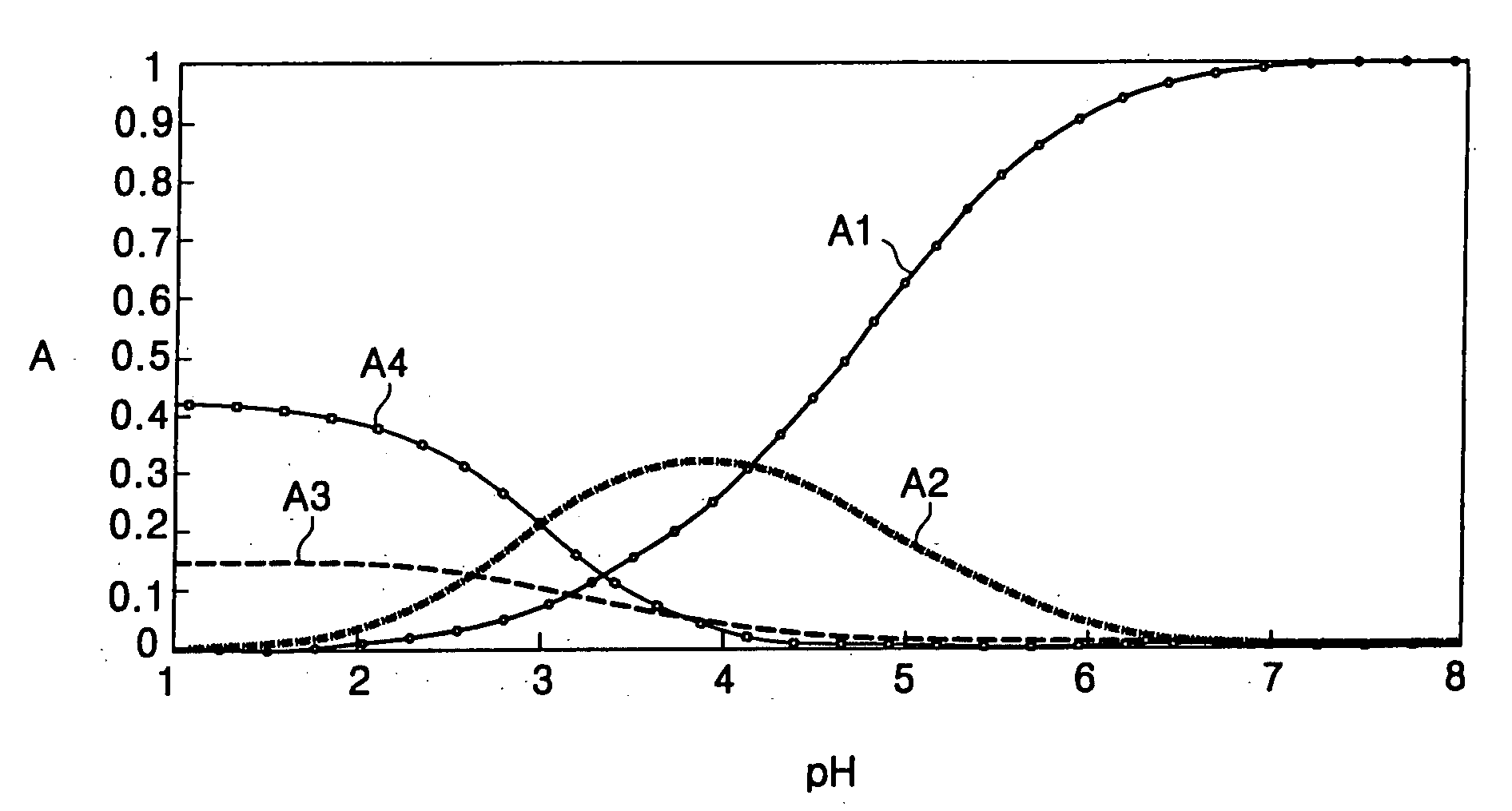
[0089] Example embodiment(s) of FIGS. 10 through 12 represent cross-sectional views illustrating fabricating a semiconductor device using the microelectronic cleaning agent in accordance with example embodiments of the present invention.

[0090] Referring to the example embodiment(s) of FIG. 10 of the present invention, a device isolation layer 101 for defining an active area may be formed on a desired area of a semiconductor substrate 100. The semiconductor substrate 100 may be a silicon wafer or a silicon on insulator (SOI) substrate. The device isolation layer 101 may be formed of a silicon oxide layer using, for example, a high density plasma chemical vapor deposition (HDPCVD) method. Other suitable device isolation layer forming processes may be used.

[0091] According to the example embodiment(s) of FIG. 10 of the present invention, a dielectric layer 103 may be formed on the semiconductor substrate 100 having the device isolation layer 101. The dielectric layer 103 may be formed...


PUM


Abstract

According to an example embodiment of the present invention, the microelectronic cleaning agent may include a fluoride component, an acid component, a chelating agent, a surfactant and water. Example embodiments of the present invention provide a microelectronic cleaning agent which can selectively remove, for example, a high-k dielectric layer. The microelectronic cleaning agent includes from about 0.001 weight % to about 10 weight % of a fluoride component, from about 0.001 weight % to about 30 weight % of an acid component, from about 0.001 weight % to about 20 weight % of a chelating agent, from about 0.001 weight % to about 10 weight % of a surfactant, and water (H2O). The water may comprise the remainder of the cleaning agent. According to another embodiment of the present invention, a method of fabricating a semiconductor device using the microelectronic cleaning agent is also provided.

Description

PRIORITY STATEMENT [0001] This application claims priority under 35 U.S.C. §119 of Korean Patent Application No. 10-2005-0009254, filed on Feb. 01, 2005, in the Korean Intellectual Property Office (KIPO), the entire contents of which are incorporated herein by reference. BACKGROUND OF THE INVENTION [0002] 1. Field of the Invention [0003] Example embodiments of the present invention relate to a composition of a surface treatment agent used, for example, for fabricating a semiconductor device. More particularly, according to example embodiments of the present invention, a microelectronic cleaning agent is provided (which may be used in processes, for example, of wet etching and / or cleaning an oxide layer) and a method of fabricating a semiconductor device using the same is provided. [0004] 2. Description of the Related Art [0005] In a semiconductor device, an oxide layer may be used for a variety of components, for example, a gate dielectric layer and / or a capacitor dielectric layer. ...

Claims


Application Information

Patent Timeline
IPC IPC(8): C11D7/32
CPCC11D3/042C11D3/30C11D3/33C11D7/08C11D7/265C11D7/3209C11D7/3218C11D7/3245C11D11/0047C11D2111/22E06B7/36E06B7/215E06B3/02E05Y2800/41
Inventor KIM, SANG-YONGCHA, JI-HOONHONG, CHANG-KICHOI, SANG-JUNSHIM, WOO-GWANBAEK, KUI-JONGKIM, SUNG-BAEKIM, HYUN-TAKLEEHAN, WOONGLIM, JUNG-HUN
Owner SAMSUNG ELECTRONICS CO LTD
Learn More