Intracardiac catheter and method of use

a catheter and intracardiac technology, applied in the field of intracardiac catheters and methods, can solve the problems of time-consuming and difficult implanting of pacemakers, irregular heartbeat, and current process of implanting, and achieve the effect of occlude the blood flow in the vein

Inactive Publication Date: 2006-08-03
KELLY J TUCKER M D
View PDF7 Cites 21 Cited by
  • Summary
  • Abstract
  • Description
  • Claims
  • Application Information

AI Technical Summary

Benefits of technology

[0015] In still another embodiment, the invention provides methods for locating an aberrant electrical conduction pattern in the heart using an invention catheter that has two or more electrodes in the distal end portion of the body by inserting a guidewire into one of the lumens of the invention catheter to form a guidewire-containing balloon catheter; percutaneously inserting the guidewire-containing balloon catheter into a vein of the heart; inflating the balloon to occlude the blood flow in the vein; injecting a radiographic dye into the vein through a lumen of the guidewire-containing balloon catheter, wherein the occlusion of the blood flow by the balloon causes retrograde flow of the blood and the dye into the surrounding connected venous structure of the vein, including branches of the vein; and imaging the vein and connected venous structure containing the radiographic dye so as to obtain a map of the vein and the surrounding connected venous structure, including branches of the vein.

Problems solved by technology

When the SA node ceases to function or functions improperly, the heartbeat can become irregular.
Current processes to implant the leads and, consequently, to implant the pacemakers for biventricular pacing are time-intensive and difficult.
One step that is extremely difficult is the placement of a pacemaker lead into the coronary sinus or left ventricle.
The difficulty of this task stems from the number of branches of the coronary sinus and the angles at which these branches project form the body of the coronary sinus.
Still another type of cardiac catheter provides a geographical map of the heart, but cannot map the path of a coronary vessel until the catheter is physically inserted into the vessel and therefore does not provide means for mapping the branches of the venous system that lead into the main vessels.

Method used


Image

  • Intracardiac catheter and method of use
  • Intracardiac catheter and method of use
  • Intracardiac catheter and method of use

Examples


Embodiment Construction

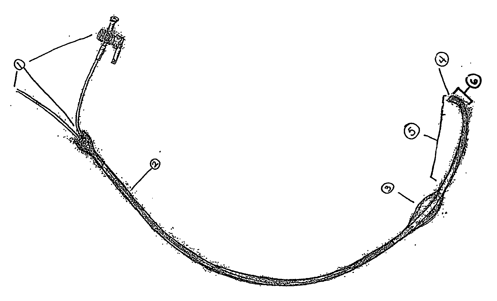
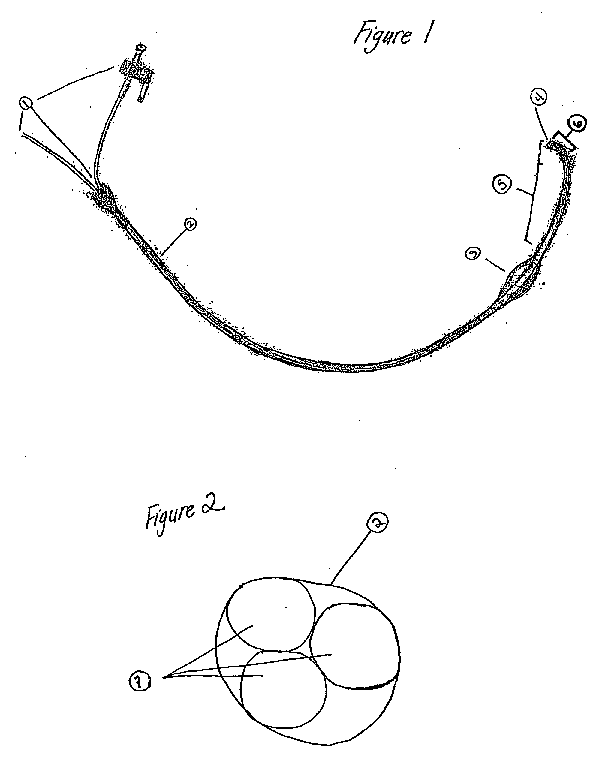
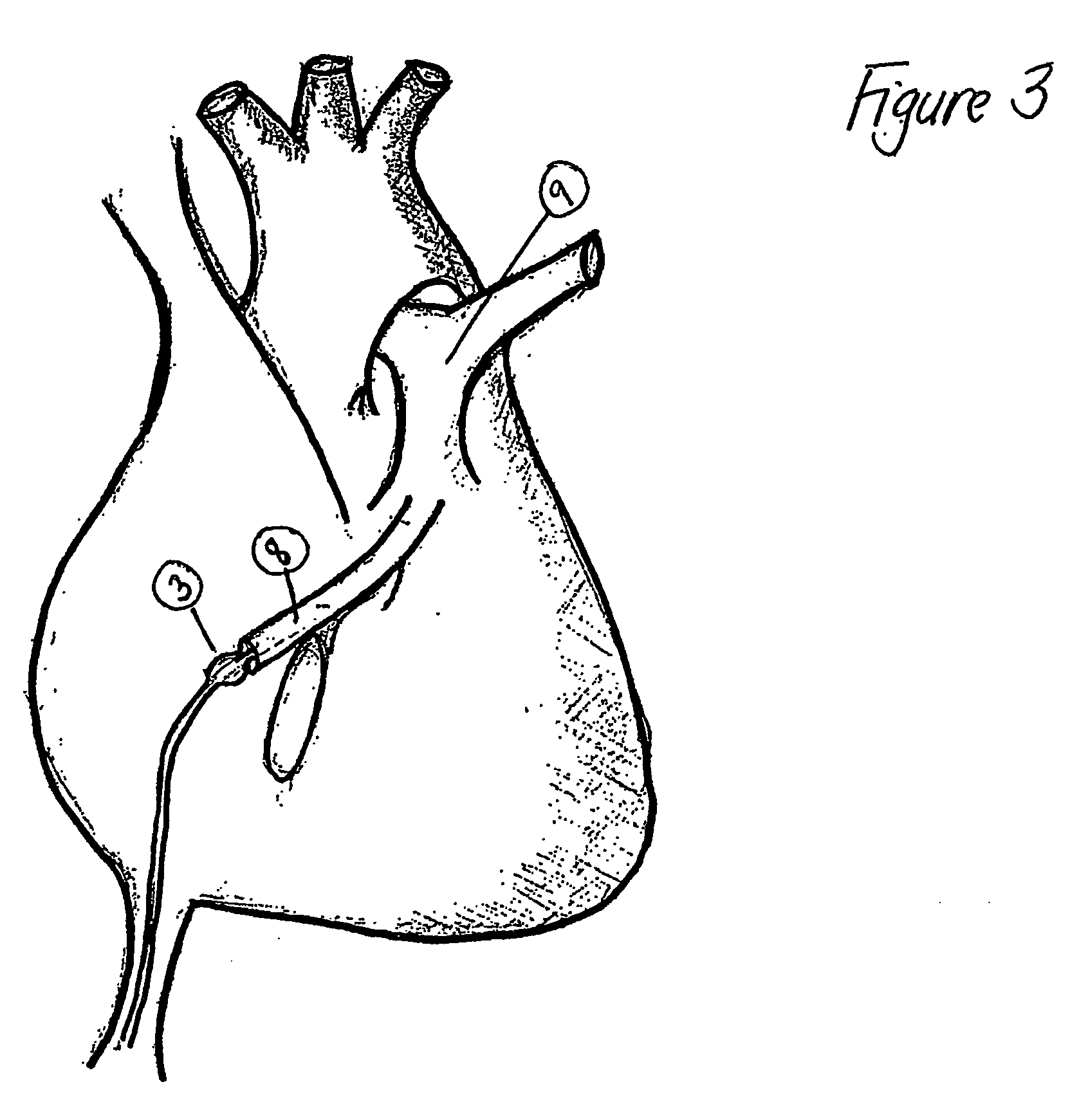
[0026] The invention catheter is for use in evaluation of coronary sinus or pulmonary vein venography to further elucidate the anatomy of the structures. A catheter of the present invention provides advantages over catheters previously used, in that the invention catheter does not use electrical activation, the catheter does not have a sheath and that the balloon, when inflated, completely occludes the vessel, and causes a retrograde flow of any injected media into the vessel, the branches and surrounding connected structures thereof.

[0027]“Venography” as used herein is a test that provides an image of the veins after a radiopaque substance, such as a radiographic dye, is injected into the subject's vein. The test is an invasive insertion of an invention catheter, in which a radiographic substance is injected into a vein in which the catheter is positioned against the blood flow of the vein. The inflated balloon of the catheter occludes the vein and causes retrograde flow into the ...


PUM


Abstract

The invention provides a cardiac balloon catheter and methods of using the same in the process of venography in the coronary sinus and pulmonary vein of the heart. The catheter has a flexible body containing a curved distal portion, at least three lumens running the length of the body each with a port of entry at the proximal end, an inflatable balloon located proximally of the curved distal portion of the body and port of exit of at least one of the lumens located at a distal end. Optionally, the catheter may contain up to ten pairs of bipolar electrodes. The invention provides methods for using the catheter to generate a geographic may of a venous structure of the heart and to generate an electrical map of the electrical conduction patterns of the heart for locating an aberrant electrical conduction pattern. Additionally, the invention catheter can be used in placement of pacemaker leads in the left ventricle for biventricular pacing of the heart.

Description

BACKGROUND OF THE INVENTION [0001] 1. Field of the Invention [0002] The invention relates generally to cardiac catheters and methods of use and, more specifically, to use of the cardiac catheter in methods for mapping the anatomy or electrical conduction patterns of a cardiac chamber and surrounding connected vein branches. [0003] 2. Background Information [0004] Subjects with irregularities in their circulatory system, due to a dysfunction of the heart, may require one or more of a number of procedures to remedy that dysfunction. Such procedures may include cardiac catheterization. In cardiac catheterization a catheter is inserted into a blood vessel through a distant percutaneous opening and fed through that blood vessel to the heart. By catheterization, either diagnostic or therapeutic procedures may be performed with minimal invasiveness. Diagnostic tests may include determination of pressure within the heart, the taking of blood samples, the taking of pictures of the blood in t...

Claims


Application Information

Patent Timeline
Patent Type & Authority Applications(United States)
IPC IPC(8): A61B6/00A61B5/00A61B5/042A61F2/958A61MA61M25/00
CPCA61B5/0422A61M25/0041A61M25/10A61M2025/004A61B5/287
Inventor TUCKER, KELLYJ
Owner KELLY J TUCKER M D
Why Eureka
Try Eureka