
System and method for numerically exploiting symmetry when using the boundary element method to perform computer-aided engineering

a numerical exploiting and boundary element technology, applied in the field of computer-aided engineering and simulation, can solve the problems of large amount of memory, high computational hardware and large computational hardware, and the inability to perform detailed electromechanical behavior simulation, etc., to achieve the effect of maximizing analytical efficiency

Inactive Publication Date: 2006-08-03
COVENTOR
View PDF0 Cites 4 Cited by
  • Summary
  • Abstract
  • Description
  • Claims
  • Application Information

AI Technical Summary

Benefits of technology

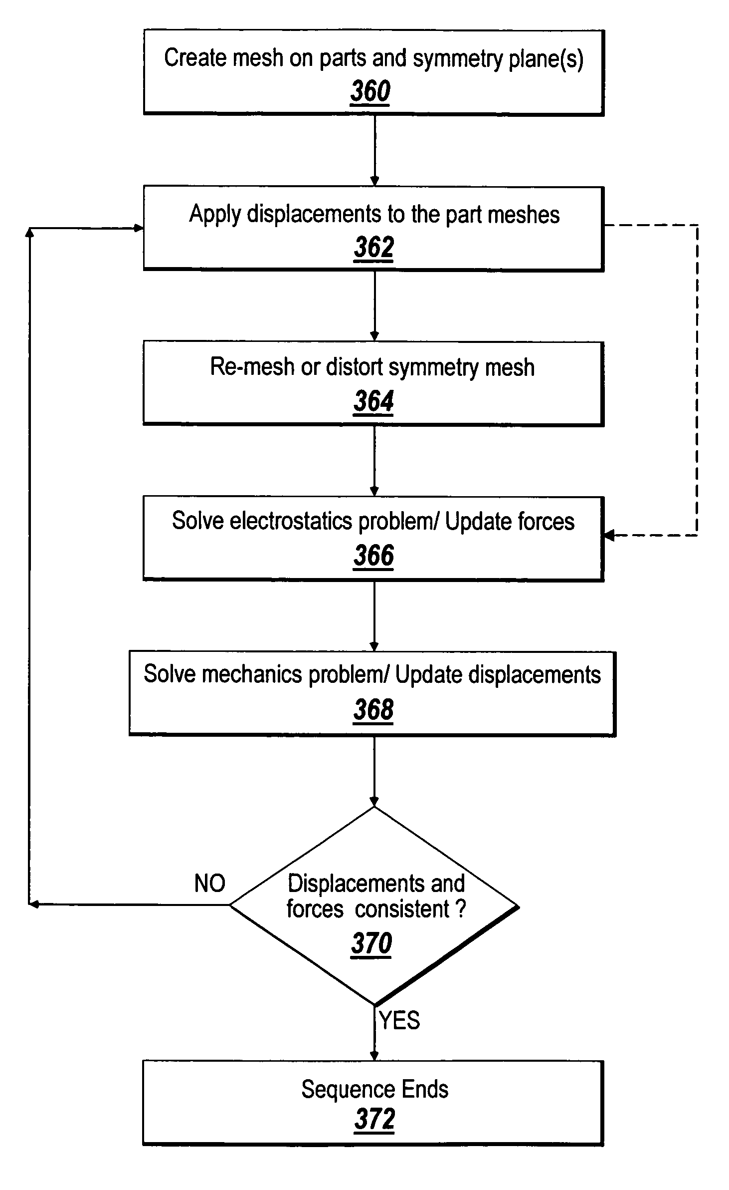
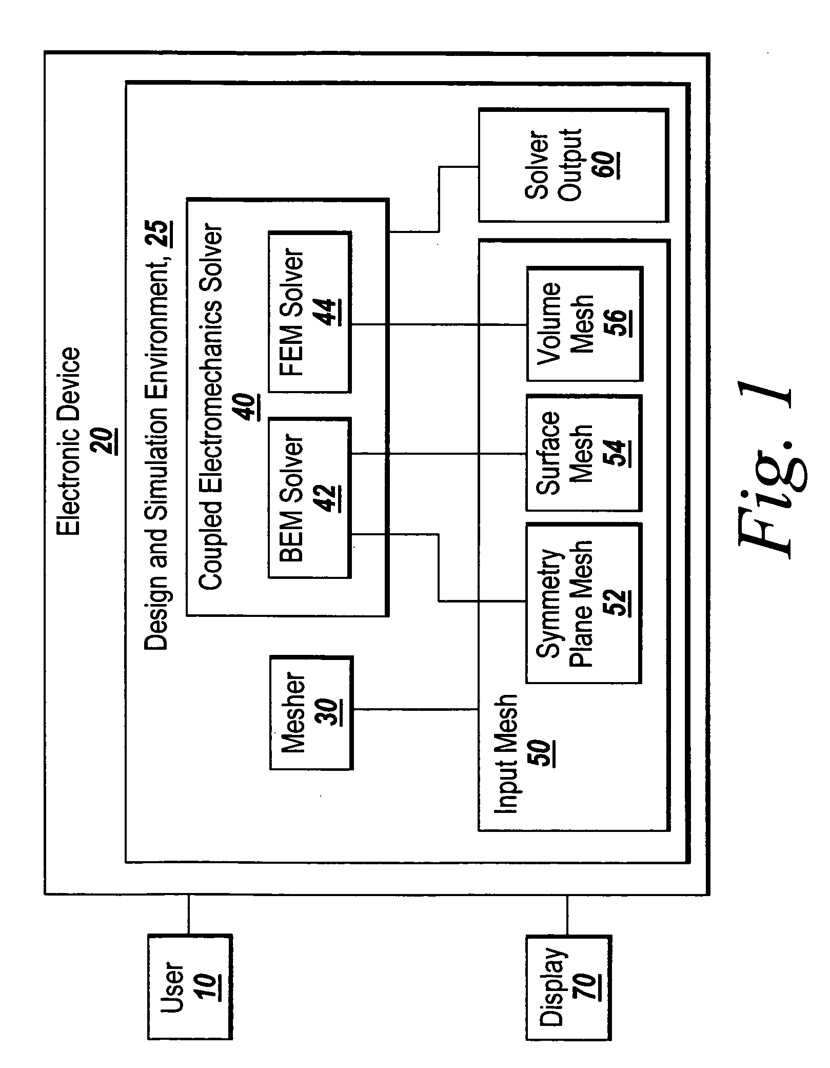
[0011] The illustrative embodiment of the present invention provides a method of numerically exploiting symmetry in a coupled electromechanical analyses while still preserving the advantages of the hybrid BEM / FEM approach previously established for non-symmetric problems. The present invention allows advantageous acceleration techniques that maximize analytical efficiency to be employed for the analysis of devices with deformable or moving parts. The illustrative embodiment of the present invention is particularly applicable to the simulation of MEMS (microelectromechanical systems) and other complicated devices that depend on effects from multiple physical domains.

Problems solved by technology

However, performing simulations of virtual models with CAE software can be expensive, since detailed simulation of complex electrical, mechanical, and fluidic behavior often requires high-cost computational hardware and large amounts of memory and processing time to achieve accurate results.
Detailed simulation of electromechanical behavior is an example of a costly and time-consuming computational analysis, because consistent electrostatic and mechanical solutions are found by iteration for any given applied voltage(s).
However, this introduces a requirement to distort, or even re-create the mesh on the symmetry plane during a coupled electromechanical analysis because of the movement or deformation of the solid parts.
Unfortunately, this means that as the parts move or deform, the regions that are the intersections of the parts and the symmetry plane(s) move or distort as well.
This necessitates undesirable mesh distortion or re-generation of the mesh on the symmetry plane(s).

Method used


Image

  • System and method for numerically exploiting symmetry when using the boundary element method to perform computer-aided engineering
  • System and method for numerically exploiting symmetry when using the boundary element method to perform computer-aided engineering
  • System and method for numerically exploiting symmetry when using the boundary element method to perform computer-aided engineering

Examples


Embodiment Construction

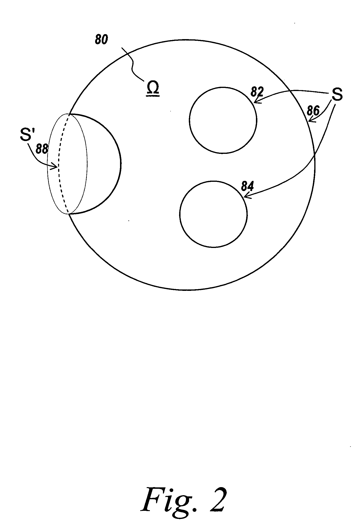
[0027] The illustrative embodiment of the present invention enables the rapid simulation of multi-domain devices such as MEMS. The present invention allows a hybrid BEM / FEM analysis of moving device parts to utilize time saving symmetry principles without requiring multiple episodes of re-meshing of any of the parts or the symmetry plane(s). An altered use of Green's theorem enables parts to move during a simulation without affecting the mesh on the symmetry plane(s) as would conventionally be the case. The present invention is thus particularly applicable to the simulation of MEMS and other multi-domain devices with moving parts.

[0028] Numerical PDE solvers take as input a discrete element model that represents the continuous device geometry and some constraints such as boundary conditions or initial conditions. These discrete elements comprise a mesh, and subdivide the large, complicated, geometric shapes of the device into small primitive shapes such as tetrahedra in volumes and...


PUM


Abstract

A method of numerically exploiting symmetry in a coupled electromechanical analysis, while still preserving the previously established advantages of the hybrid BEM / FEM approach for performing such analyses without exploiting symmetry is disclosed. The present invention allows advantageous acceleration techniques, which maximize analytical efficiency, to be employed for the analysis of systems with moving or deformable parts. The illustrative embodiment of the present invention is particularly applicable to simulating the physical behavior of MEMS (microelectromechanical system) devices and other complicated multi-domain devices.

Description

FIELD OF THE INVENTION [0001] The illustrative embodiment of the present invention relates generally to computer-aided engineering and simulation, and more particularly to a method of simulating the coupled electromechanical behavior of movable or deformable bodies that is useful for simulating the physical behavior of microelectromechanical systems (MEMS). BACKGROUND [0002] Computer-aided engineering (CAE) software is used to simulate the behavior of virtual models of realizable devices that may include mechanical and electrical parts, and moving fluids. The predictive power of such software is routinely used in all aspects of engineering design to eliminate, as much as possible, the costly and time consuming process of building and testing physical prototypes. However, performing simulations of virtual models with CAE software can be expensive, since detailed simulation of complex electrical, mechanical, and fluidic behavior often requires high-cost computational hardware and larg...

Claims


Application Information

Patent Timeline
IPC IPC(8): G06F17/10
CPCG06F17/5018G06F17/5086G06F30/17G06F30/23G06F2115/04
Inventor KORSMEYER, TOM
Owner COVENTOR
Learn More