
Method for creating and preserving snapshots in a storage system

a storage system and snapshot technology, applied in the field of snapshot function implementation, can solve the problems of large volume required, long process of searching difference, etc., and achieve the effect of reducing volume capacity

Inactive Publication Date: 2006-08-03
HITACHI LTD
View PDF5 Cites 89 Cited by
  • Summary
  • Abstract
  • Description
  • Claims
  • Application Information

AI Technical Summary

Benefits of technology

[0016] Therefore, an object of the present invention is to provide the technique capable of reducing the volume capacity required to store the copy of the snapshot and to copy the snapshot at processing amount which is independent of the number of file of the file system.

Problems solved by technology

As a result, there is a problem that a large number of volumes are required when the number of snapshots to be stored is increased.
However, since it is necessary to search the difference in each file, it takes a long time for the process of searching the difference in the case of the file system having a large number of files.

Method used


Image

  • Method for creating and preserving snapshots in a storage system
  • Method for creating and preserving snapshots in a storage system
  • Method for creating and preserving snapshots in a storage system

Examples


first embodiment

[0043] This embodiment will describe an example in which the saved snapshot is referenced by using the block copy management table in the volume in which the snapshot is saved.

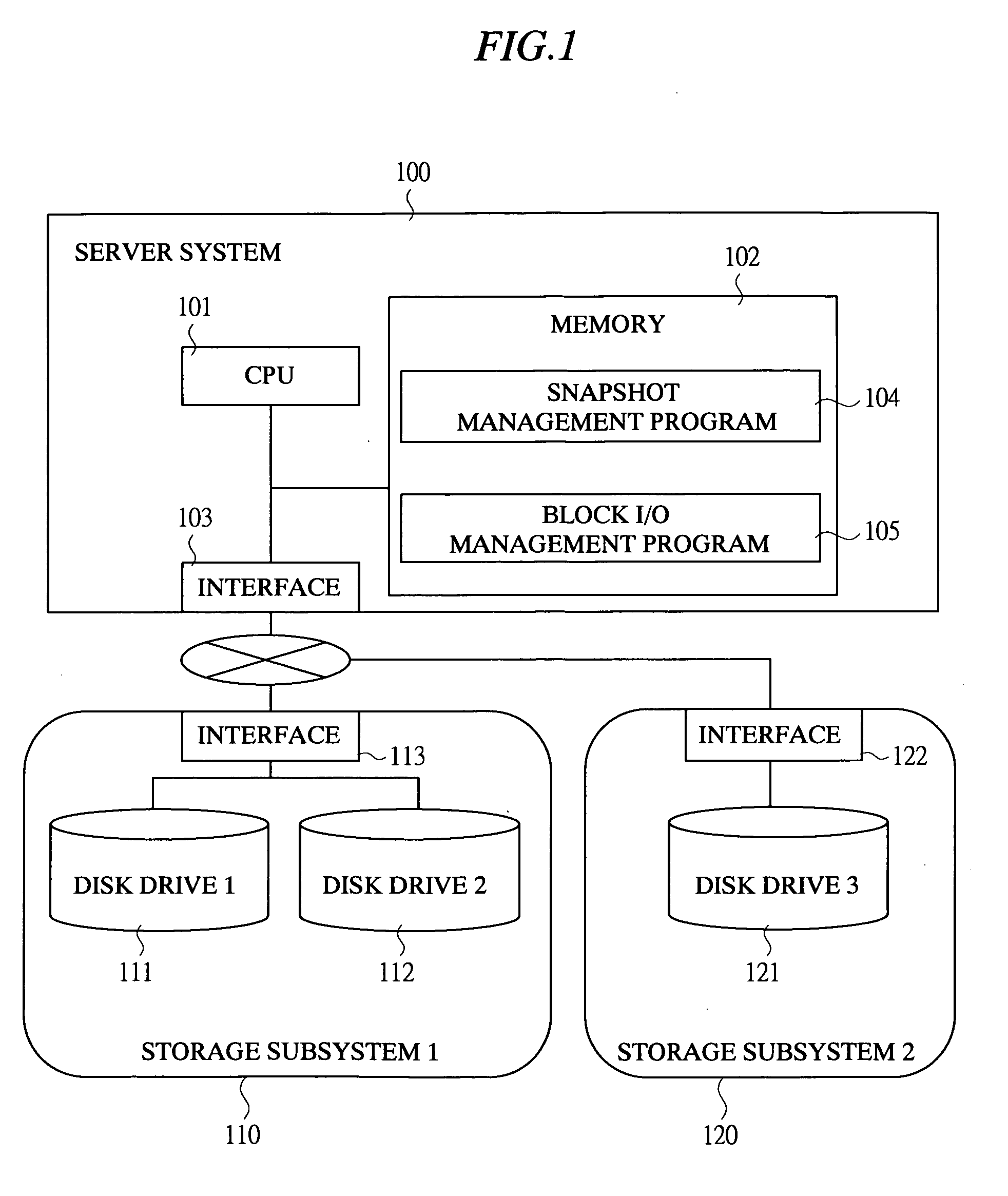
[0044]FIG. 1 is a block diagram showing an example of the system configuration of the storage system according to the first embodiment of the present invention.

[0045] The storage system of this embodiment comprises a server system 100, a storage subsystem 110, and a storage subsystem 120.

[0046] The server system 100 is provided with a CPU 101 having a function as a control unit for performing processes, a memory 102 for retaining the data which is required for the processes performed in the server system 100 and software which is executed by the CPU 101, and an interface 103 having a function as a connection device for connecting the server system 100 and the storage subsystems 110 and 120 so as to perform data transfer between them.

[0047] Usually, various programs are operated on the server system. For ex...

second embodiment

[0104] In this embodiment, the method of saving the snapshot in which the data copy from the operation volume other than the copy of difference data is reduced will be described.

[0105] The configuration of the system is identical to that of the first embodiment. However, the snapshot saving volume is changed so that a reference destination snapshot is saved therein. In addition, the saving volume separation subprogram and the saving volume reconnection subprogram are changed in the following manner.

[0106] In the separation of the volume, the saving volume separation subprogram copies the block not copied as the difference data from the operation volume. Instead, the number of the latest snapshot in the snapshot saving volume is saved together with the block copy management table. Then, in the block copy management table in the memory, the snapshot corresponding to the saved number is made undeletable and the copy of the difference data is continued.

[0107] The process of reading t...


PUM


Abstract

The reduction of the volume capacity necessary to copy the snapshot can be achieved. When an operation volume is updated, the data before the update is saved in a difference storing volume, and the data of the two volumes, that is, the operation volume and the difference storing volume are combined to constitute the snapshot. In order to constitute the snapshot, the data necessary to constitute the snapshot is copied to the snapshot saving volume by using the block copy management table in which the data location in the operation volume and the difference storing volume is recorded, and another block copy management table for retaining the data location after the copy is saved in the volume. The saved snapshot can be referenced by accessing the snapshot saving volume, to which the data constituting the snapshot is copied, by using the snapshot read program.

Description

CROSS-REFERENCE TO RELATED APPLICATION [0001] The present application claims priority from Japanese Patent Application JP 2005-23546 filed on Jan. 31, 2005, the content of which is hereby incorporated by reference into this application. TECHNICAL FIELD OF THE INVENTION [0002] The present invention relates to a technique for realizing a snapshot function in a storage system, and more particularly, it relates to a technique effectively applied to the method of creating and keeping a snapshot by using a logical volume manager. BACKGROUND OF THE INVENTION [0003] As the use of information systems has been expanding more and more, the capacity of the storages for storing the data has been also increasing. According to this, the value of the data stored in the storages rises and the destruction of data due to unauthorized accesses to data or erroneous operations results in a great loss in the management of information systems. Therefore, data protection functions become more and more impor...

Claims


Application Information

Patent Timeline
Patent Type & Authority Applications(United States)
IPC IPC(8): G06F12/16
CPCG06F3/0608G06F3/0611G06F3/0619G06F3/0631G06F3/0641G06F3/065G06F3/0659G06F3/0689G06F11/1435G06F2201/84
Inventor SUTOH, ATSUSHI
Owner HITACHI LTD
Learn More