Method and system for controlling an array of point-of-load regulators and auxiliary devices

a point-of-load regulator and array technology, applied in the direction of liquid/fluent solid measurement, instruments, sustainable buildings, etc., can solve the problems of large circuit board area, inability to deliver relatively high current at low voltage over a relatively long distance, and congestion of signal line routing

Inactive Publication Date: 2006-08-03
BEL POWER SOLUTIONS INC
View PDF10 Cites 48 Cited by
  • Summary
  • Abstract
  • Description
  • Claims
  • Application Information

AI Technical Summary

Benefits of technology

[0011] In an embodiment of the invention, the power control system comprises at least one POL regulator, at least one auxiliary device, a serial data bus operatively connecting the POL regulator and the auxiliary device, and a system controller adapted to exchange digital data with the POL regulator and auxiliary device via the serial data bus. The auxiliary device may include a power regulation device, a switching device, a motor control device, a temperature control device, and / or a peripheral device. At least one auxiliary device controller may be operatively coupled between the auxiliary device and the serial data bus. The auxiliary device controller may be integrated with the system controller, or may be external to the system controller. The auxiliary device controller may further comprise at least one register adapted to store the programming data, with the programming data including at least one of turn-on delay, turn-off delay, polarity of input / output signals, fault configuration, and group membership. The auxiliary device controller may be further adapted to receive monitoring data from the auxiliary device, with the auxiliary device controller communicating the monitoring data to the system controller via the serial data bus.
[0012] In an alternative embodiment of the invention, a method of operating a power control system comprises: (a) generating programming parameters for at least one point of load (POL) regulator and at least one auxiliary device; (b) transmitting programming data based on the programming parameters serially over a common data bus operatively connected to the at least one POL regulator and the at least one auxiliary device; and (c) operating the at least one POL regulator and the at least one auxiliary device in accordance with the programming data. The programming parameters may be received from a user, such as using a graphical user interface. The programming data would be stored in a memory contained in the at least one POL regulator and the at least one auxiliary device, or in a memory contained in a system controller operatively coupled to the at least one POL regulator and the at least one auxiliary device. The method may further include generating monitoring data regarding operating status of the at least one POL regulator and the at least one auxiliary device, and transmitting the monitoring data serially over the common data bus.

Problems solved by technology

With the increasing complexity of electronic systems, it is common for an electronic system to require power provided at several different discrete voltage and current levels.
It is undesirable to deliver relatively high current at low voltages over a relatively long distance through an electronic device for a number of reasons.
First, the relatively long physical run of low voltage, high current lines consumes significant circuit board area and congests the routing of signal lines on the circuit board.
Second, the impedance of the lines carrying the high current tends to dissipate a lot of power and complicate load regulation.
Third, it is difficult to tailor the voltage / current characteristics to accommodate changes in load requirements.
A drawback with such a control system is that it adds complexity and size to the overall electronic system.
In some cases, it is desirable to coordinate the control over these auxiliary devices in concert with the POL regulators of the power system, such as to control the operation of a fan in synchronism with activation of a POL regulator; however, conventional distributed power system do not provide flexibility to control other auxiliary devices in addition to POL regulators.

Method used


Image

  • Method and system for controlling an array of point-of-load regulators and auxiliary devices
  • Method and system for controlling an array of point-of-load regulators and auxiliary devices
  • Method and system for controlling an array of point-of-load regulators and auxiliary devices

Examples


Embodiment Construction

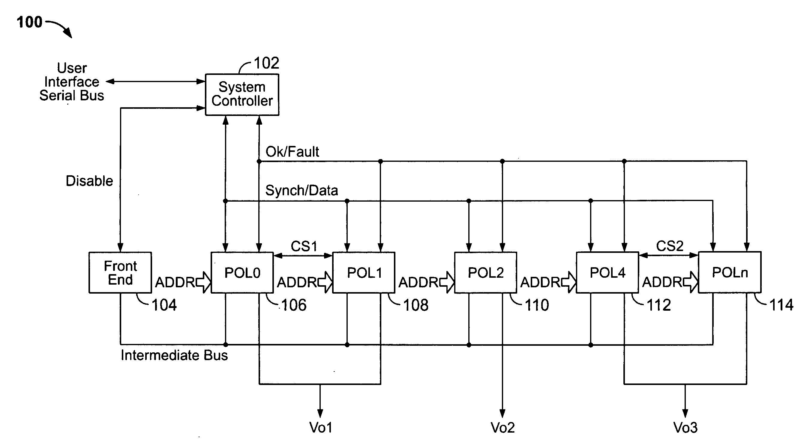
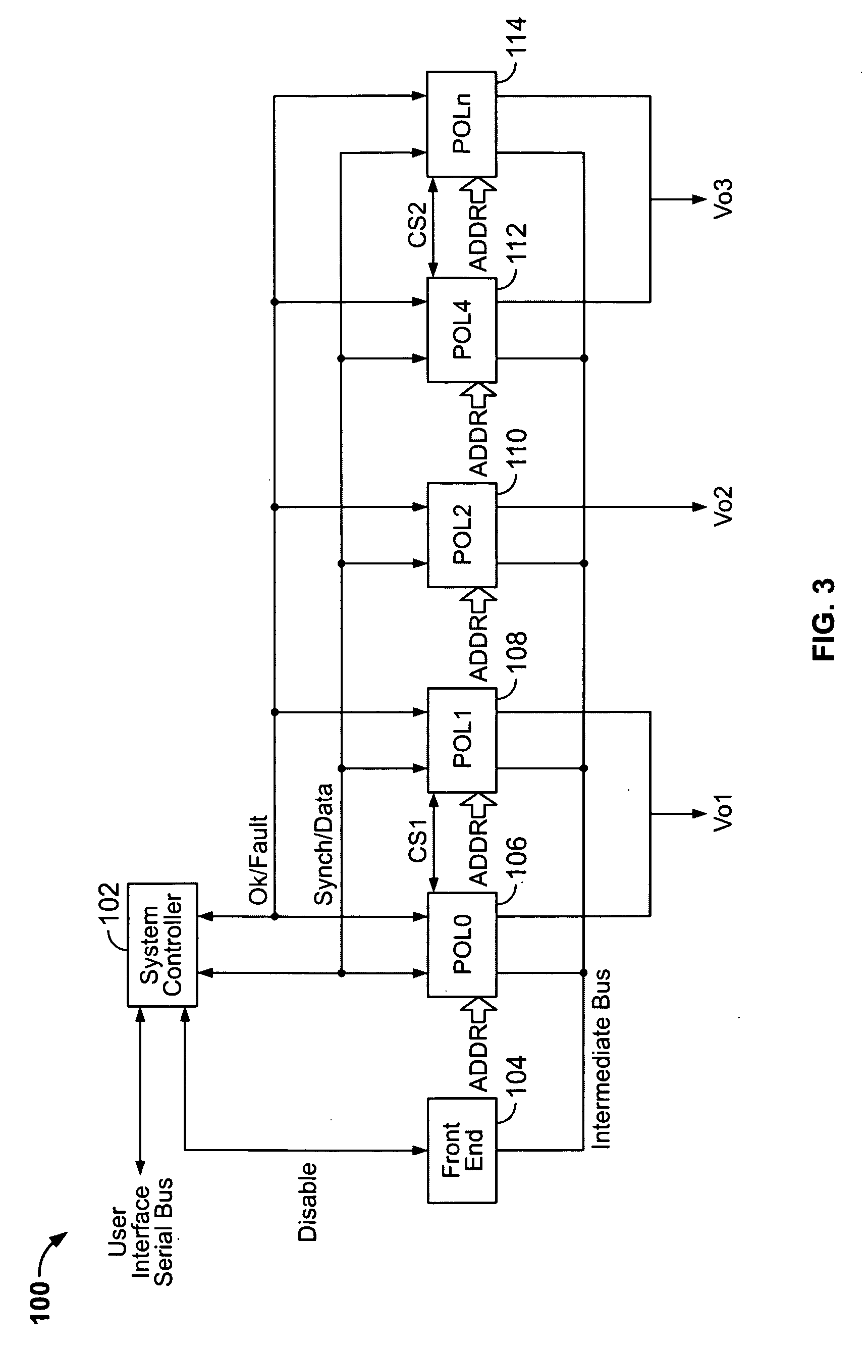
[0021] The present invention provides a system and method for controlling and monitoring POL regulators and auxiliary devices within a distributed power system. In the detailed description that follows, like element numerals are used to describe like elements illustrated in one or more figures.

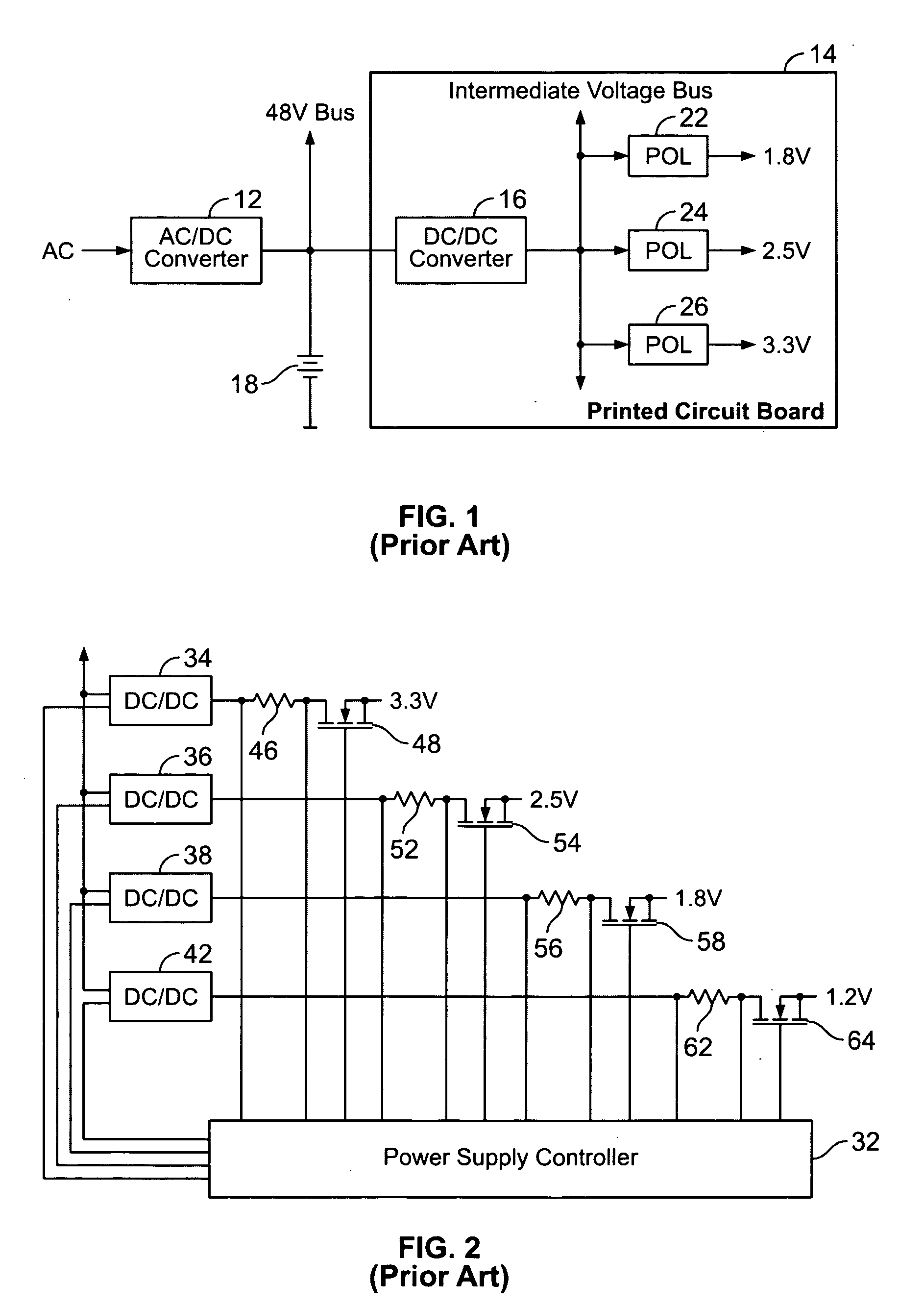
[0022] Referring first to FIG. 1, a prior art distributed power delivery system is shown. The prior art distributed power deliver system includes an AC / DC converter 12 that converts the available AC power into a primary DC power source, e.g., 48 volts. The primary DC power source is connected to a primary power bus that distributes DC power to plural electronic systems, such as printed circuit board 14. The bus may be further coupled to a battery 18 providing a back-up power source for the electronic systems connected to the primary power bus. When the AC / DC converter 12 is delivering DC power into the primary power bus, the battery 18 is maintained in a fully charged state. In the event of l...


PUM


Abstract

A power control system comprises at least one POL regulator, at least one auxiliary device, a serial data bus operatively connecting the POL regulator and the auxiliary device, and a system controller adapted to exchange digital data with the POL regulator and auxiliary device via the serial data bus. The auxiliary device may include a power regulation device, a switching device, a motor control device, a temperature control device, and/or a peripheral device. At least one auxiliary device controller may be operatively coupled between the auxiliary device and the serial data bus. The auxiliary device controller may be integrated with the system controller, or may be external to the system controller. The auxiliary device controller may further comprise at least one register adapted to store the programming data, with the programming data including at least one of turn-on delay, turn-off delay, polarity of input/output signals, fault configuration, and group membership. The auxiliary device controller may be further adapted to receive monitoring data from the auxiliary device, with the auxiliary device controller communicating the monitoring data to the system controller via the serial data bus.

Description

RELATED APPLICATION DATA [0001] This application claims priority as a continuation-in-part pursuant to 35 U.S.C. § 120 to patent application Ser. No. 10 / 326,222, filed Dec. 21, 2002.BACKGROUND OF THE INVENTION [0002] 1. Field of the Invention [0003] The present invention relates to power control systems, or more particularly, to a method and system to control, program and monitor an array of point-of-load regulators and other auxiliary devices. [0004] 2. Description of Related Art [0005] With the increasing complexity of electronic systems, it is common for an electronic system to require power provided at several different discrete voltage and current levels. For example, electronic systems may include discrete circuits that require voltages such as 3v, 5v, 9v, etc. Further, many of these circuits require a relatively low voltage (e.g., 1v), but with relatively high current (e.g., 100 A). It is undesirable to deliver relatively high current at low voltages over a relatively long di...

Claims


Application Information

Patent Timeline
Patent Type & Authority Applications(United States)
IPC IPC(8): G06F1/26H02J1/08H02J1/10H02J13/00
CPCG06F1/189G06F1/3203G06F1/3253G06F1/3287G06F1/329H02J1/08Y02B60/144H02J13/0003H02J2001/008H02M2001/008Y02B60/1235Y02B60/1282H02J1/102H02J2310/16H02J1/082H02J13/00004Y02D10/00H02M1/008H02J13/00016G06F1/00G06F1/26G06F11/30G06F13/00Y02A30/60
Inventor CHAPUIS, ALAINGUZ, MIKHAIL
Owner BEL POWER SOLUTIONS INC
Why Eureka
Try Eureka