High static thrust valveless pulse-jet engine with forward-facing intake duct

a valveless, forward-facing technology, applied in the direction of machines/engines, jet propulsion plants, intermittent jet plants, etc., can solve the problems of single intake tube and insufficient air aspiration by itself to achieve a high burn rate during static operation, so as to maximize static thrust and improve dynamic thrust , the effect of improving performan

Inactive Publication Date: 2006-08-10
SSTREETCAR MICHAEL A
View PDF2 Cites 8 Cited by
  • Summary
  • Abstract
  • Description
  • Claims
  • Application Information

AI Technical Summary

Benefits of technology

[0006] Starting with a preferred embodiment of my engine covered in U.S. Pat. No. 6,216,446, my objective was to find novel modifications to improve performance, specifically, to maximize static thrust, improve dynamic thrust, and, if possible, lower fuel consumption under both conditions. This meant discovering novel modifications that would increase the ability of the engine to capture more air, since more air would enable more fuel to be burned in a given moment, resulting in higher throttling, greater static thrust, and a lowering of specific fuel consumption, due to burning of leaner air-fuel mixtures. The primary focus of continued testing was to increase static thrust, by studying and testing modifications to the intake duct. Because the engine is a pulse-je...

Problems solved by technology

Because it employs only one aspiration stage, the single intake tube, by itself can not aspirate ...

Method used


Image

  • High static thrust valveless pulse-jet engine with forward-facing intake duct
  • High static thrust valveless pulse-jet engine with forward-facing intake duct
  • High static thrust valveless pulse-jet engine with forward-facing intake duct

Examples


Embodiment Construction

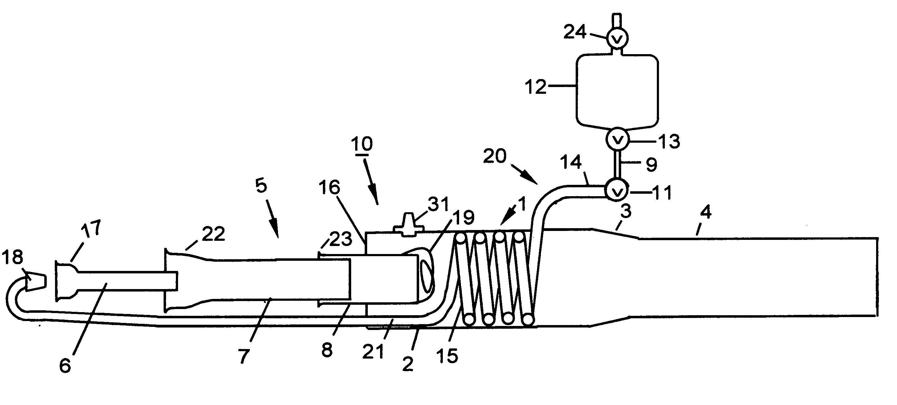
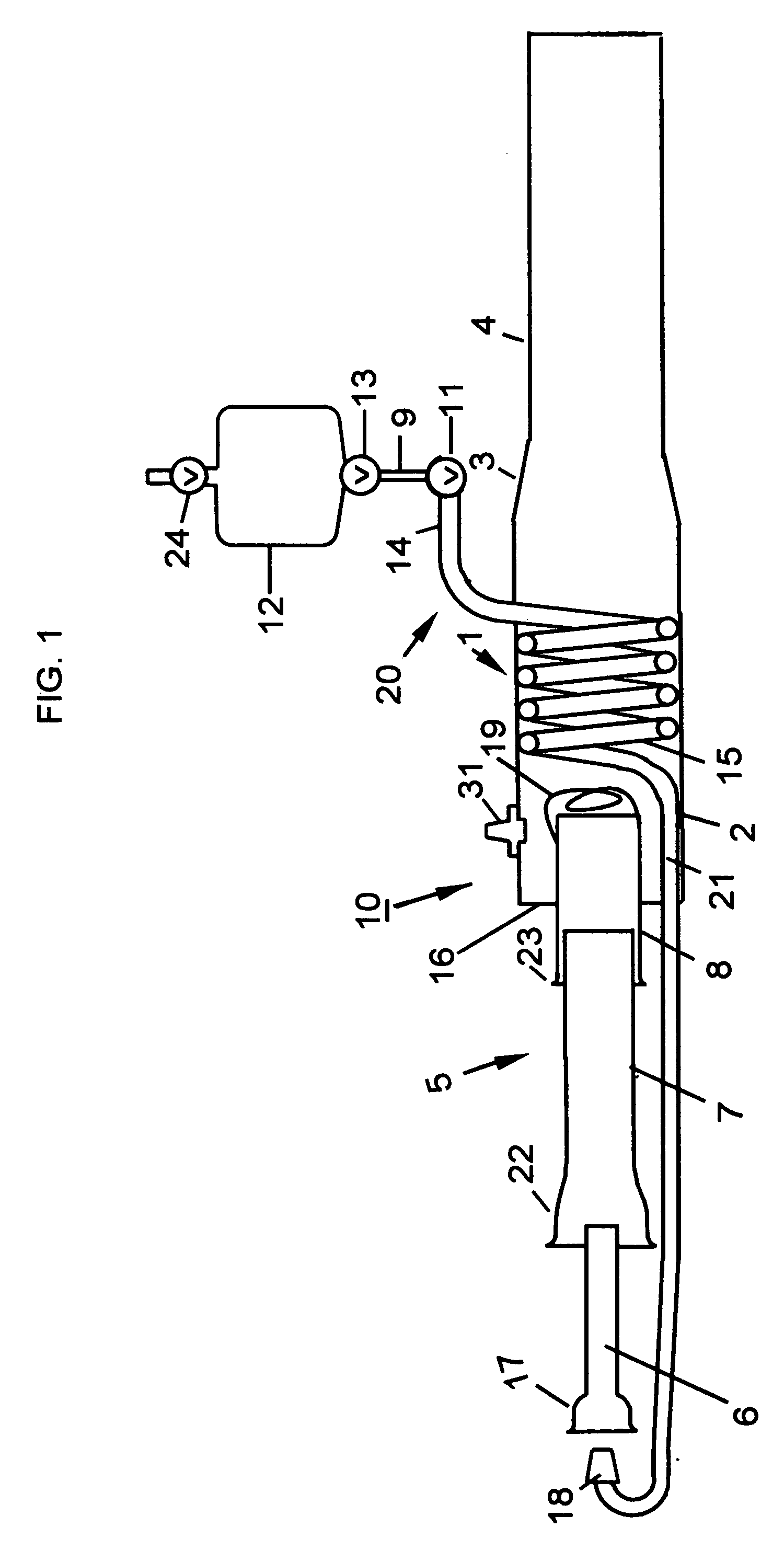
[0010] Referring now to FIG. 1, there is illustrated a valveless, self-starting, self-aspirating pulse-jet engine 10, which is comprised of a cylindrical combustor tube 1, an intake duct 5, a fuel supply means 20, and a flame holder 19. The combustor tube 1 has a length of 5.5 times the diameter of the combustion chamber 2. Engines of this invention operate successfully when the combustor tube 1 has a length of 4-9 times the diameter of the combustion chamber 2, but for best operation, the combustor tube 1 length should fall in a range of 5-7 times the diameter of the combustion chamber 2. I have found that engine length is not a critical dimension; when adjusted to the preferred length, engines of this invention may operate better but may not necessarily develop more static or dynamic thrust. The combustor tube 1 consists of a cylindrical combustion chamber 2, having a flat forward face 16, communicating with a reducing cone 3, which is connected to an exhaust tail tube 4. Engines ...


PUM


Abstract

A self-starting, self-aspirating valveless pulse-jet engine maximized to capture air during static operation. This invention is an improved adaptation of my U.S. Pat. No. 6,216,446, and continues to utilize a combustor tube, a forward-facing intake duct, a flame holder, a fuel supply means, and a spark plug to ignite the fuel-air mixture. To improve static air capture, the intake tubes of the intake duct, forward of the primary intake tube, that is joined to the combustion chamber, feature aggressively enlarged forward inlet mouths. By adjusting the relative diameters of the intake tubes that are inserted into each other, to achieve a greater difference of diameters, this adjustment, combined with aggressively enlarged intake tube mouths dramatically increases the ability of the intake duct to capture a maximum of air during static operation. Tests have shown the enlarged mouths are equally effective either as enlarged cupped mouths or as enlarged cones. Further improvement in air capture has been gained by adjusting the position of the aft end of the intake tube that is inserted inside the primary intake tube, so its position is in a range that is even with the plane created by the combustion chamber forward wall or just outside of the combustion chamber and closer to the mouth of the primary intake tube. (According to my U.S. Pat. No. 6,216,446, this intake tube was located so its aft end was inside the combustion chamber.) Further improvement in static air capture is made by specifying a diameter of the exhaust tube tail that has proved superior for air capture during static research testing. Capture of more air during static operation increases burn rate and thrust, and lowers specific fuel consumption, due to burning of leaner air-fuel mixtures. This invention also has improved thrust during dynamic operation, because the enlarged intake tube mouths capture more air during forward movement of the engine.

Description

CROSS REFERENCE TO RELATED PATENT [0001] This application claims the benefits of my U.S. Provisional Patent Application Ser. No. 60 / 651,435, filed Feb. 10, 2005, and is directly related to my U.S. Pat. No. 6,216,446. Many of the construction features and the mode of operation are identical to the above referred U.S. Pat. No. 6,216,446.BACKGROUND OF THE INVENTION [0002] 1. Field of the Invention [0003] This invention relates to tubular jet engines and pulse-jets of the valveless type that are self-starting, self-aspirating, and consist of a tubular combustor tube and a forward-facing intake duct. These engines have no moving parts and operate on gaseous volatile hydrocarbons, such as propane and ethane, or vaporized liquid fuels, such as gasoline or kerosene. Usually, these engines have an intake duct consisting of a multiplicity of intake tubes inserted into each other. Some self-starting ram jets belong to this field of invention. [0004] 2. Description of the Prior Art [0005] The c...

Claims


Application Information

Patent Timeline
IPC IPC(8): F02K7/02
CPCF02K7/02F05D2220/10
Inventor STRAM, MICHAEL A.
Owner SSTREETCAR MICHAEL A
Why Eureka
Try Eureka