[0008] Therefore, the present invention has been made in view of the above problems occurring in the prior art, and it is an object of the present invention to provide a two-stage compression heat pump system having a flash tank which induces two refrigerants to reach
thermal equilibrium smoothly, wherein the refrigerants have different states from each other and flow into the flash tank, to embody a two-stage compression cycle having complete intermediate cooling, to prevent fine droplets from flowing into a high-stage compressor in order to inhibit liquid back or liquid compression in the high-stage compressor, wherein the fine droplets are generated in the process of obtaining
thermal equilibrium, and to allow the
refrigeration oil flowing into the flash tank together with the refrigerant to be collected into the compressor in order to prevent refrigeration oil from remaining in a specific device so as to extend the life-span and enable stable operations of the device, thereby enhancing system reliability and performance.
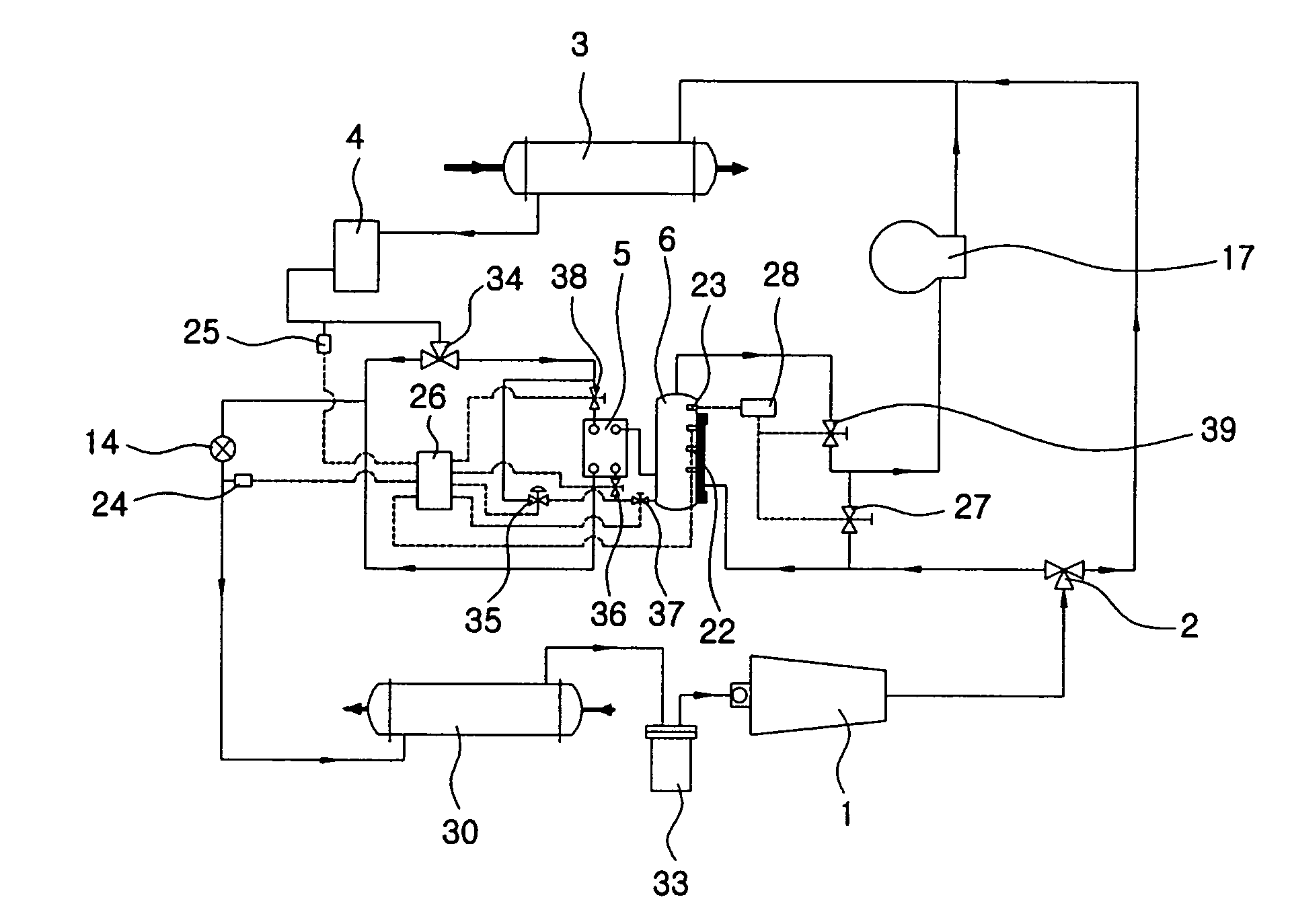
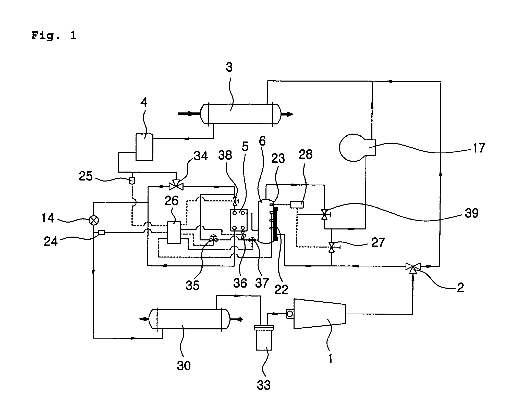
[0009] To accomplish the above object, according to one aspect of the invention, there is provided a flash tank of a two-stage compression heat pump system for cooling and heating in one system, having an intercooler that maximizes
cooling effect by increasing the degree of sub-cooling of a refrigerant sent to the flash tank and an
evaporator, the two-stage compression heat pump system serving to perform a single-stage compression cooling operation in summertime using only a low-stage compressor for stable operations, and using both the low-stage compressor and a high-stage compressor in wintertime for highly efficient operations, wherein the flash tank and the intercooler are separately allocated. The two-stage compression heat pump system comprises: a fluid-level detecting sensor mounted inside the flash tank for detecting a fluid-level of the refrigerant; an
alarm sensor for notifying a saturated state of the refrigerant filled in the flash tank; an evaporator
pressure sensor for measuring and notifying pressure of the refrigerant flowing into the evaporator; a condenser pressure sensor for measuring and notifying pressure of the refrigerant flowing out of the condenser; a flash tank fluid-level controller for receiving signals from the above sensors and controlling
intermediate pressure and the fluid-level of the flash tank; and a
bypass valve controller for controlling a bypass valve that receives signals from the alarm sensor, allowing a refrigerant to directly flow from the low-stage compressor to the high-stage compressor. The flash tank comprises: an intercooler outlet
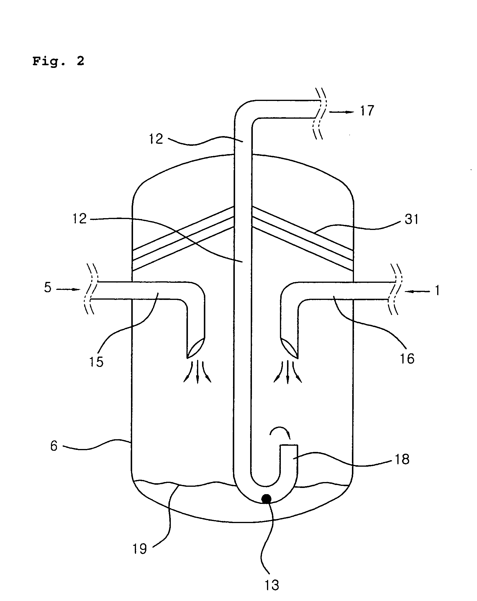
pipe mounted on one side of the flash tank; a low-stage compressor outlet
pipe mounted on the other side of the flash tank; a high-stage compressor inlet
pipe installed inside the flash tank, wherein the high-stage compressor inlet pipe has an end portion of a U-shaped pipe formed at a bottom side of the flash tank, a refrigeration oil inlet provided at a bottom side of the U-shaped pipe, and another end portion connected to the high-stage compressor; and an orifice installed so as to correspond to the refrigeration oil inlet provided at the bottom side of the U-shaped pipe, wherein the orifice is provided for filtering contaminations in the refrigeration oil.
[0010] According to another aspect of the invention, there is also a flash tank of a two-stage compression heat pump system for cooling and heating in one system, having an intercooler that maximizes
cooling effect by increasing the degree of sub-cooling of a refrigerant sent to the flash tank and an evaporator, the two-stage compression heat pump system serving to perform a single-stage compression cooling operation in summertime using only a low-stage compressor for stable operations, and using both the low-stage compressor and a high-stage compressor in wintertime for highly efficient operations, wherein the flash tank and the intercooler are separately allocated. The two-stage compression heat pump system comprises: a fluid-level detecting sensor mounted inside the flash tank for detecting a fluid-level of the refrigerant; an alarm sensor for notifying a saturated state of the refrigerant filled in the flash tank; an evaporator pressure sensor for measuring and notifying pressure of a refrigerant flowing into the evaporator; a condenser pressure sensor for measuring and notifying pressure of a refrigerant flowing out of the condenser; a flash tank fluid-level controller for receiving signals from the above sensors and controlling intermediate pressure and the fluid-level of the flash tank; and a bypass valve controller for controlling a bypass valve that receives signals from the alarm sensor, allowing a refrigerant to directly flow from the low-stage compressor to the high-stage compressor. The flash tank comprises: an intercooler outlet pipe mounted on one side of the flash tank; a low-stage compressor outlet pipe mounted on the other side of the flash tank; a helically-shaped pipe connected to the low-stage compressor outlet pipe; a refrigeration oil collecting tube connected to an end portion of the coil-shaped pipe for inducing refrigeration oil into a refrigeration
oil tank; a refrigerant vapor
discharge port formed at one side of the refrigeration oil collecting tube for discharging refrigerant vapor from the refrigeration oil collecting tube; and a high-stage compressor inlet pipe for inducing refrigerant vapor from the flash tank to the high-stage compressor.
[0012] The two-stage compression heat pump system according to the invention, in a case where the two-stage compressor and the heat pump adopt a separate type intermediate cooling method, induces a stable heat exchange within the flash tank, the heat exchange being performed between the superheated vapor discharged from a low-stage and the refrigerant that has passed through an intercooler, but not turned into a saturated vapor, prevents a liquid back or liquid compression by blocking the droplets generated in the process of heat exchange from flowing into the high-stage compressor, and allows the refrigeration oil mixed with the refrigerant vapor discharged from a low-stage to be easily collected instead of being retained in the flash tank, and thus increases system reliability through device protection, and embodies a two-stage compression cycle with complete intermediate cooling, thereby greatly improving system performance.

