
Apparatus for processing substrate

a technology for processing apparatuses and substrates, applied in the direction of liquid surface applicators, coatings, chemical vapor deposition coatings, etc., to achieve the effect of reducing the area at which the apparatus is installed and the time for processing substrates

Active Publication Date: 2006-08-10
SEMES CO LTD
View PDF9 Cites 154 Cited by
  • Summary
  • Abstract
  • Description
  • Claims
  • Application Information

AI Technical Summary

Benefits of technology

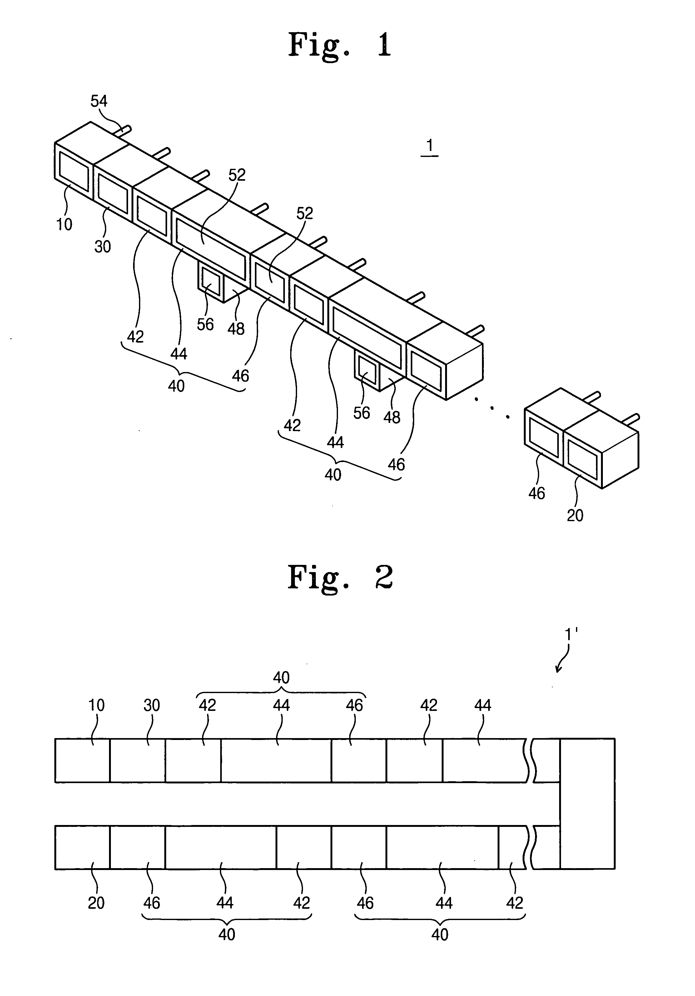
[0008] The present invention provides a substrate processing apparatus capable of efficiently carrying out a deposition process for an organic light emitting diode.
[0016] The apparatus may further include a blocking plate through which an opening facing an upper portion of the deposition material supplying member is formed. The blocking plate is installed between the substrate attached to the substrate supporter and the deposition material supplying member. The blocking plate may prevent the deposition material supplied from the deposition material supplying member from being moved through the opening of the deposition chamber or deposited at the transferring guide.
[0023] The substrate supporter may further include a guide roller that rolls along a side face of the transferring guide in order to prevent deviation of the supporting plate from the transferring guide toward a direction substantially perpendicular to a longitudinal direction of the transferring guide when the supporting plate is transferred along the transferring guide.
[0026] According to the above, a time for processing the substrate and an area at which the apparatus is installed may be reduced, and the chambers may be continuously maintained in a vacuum state when any one of the chambers is repaired.

Problems solved by technology

However, since the substrates are transferred by the robot arm, the processes require so many times to unload the substrates from the process chambers and load the substrates to the process chambers.

Method used


Image

  • Apparatus for processing substrate
  • Apparatus for processing substrate
  • Apparatus for processing substrate

Examples


Embodiment Construction

[0042] It will be understood that when an element or layer is referred to as being “on”, “connected to” or “coupled to” another element or layer, it can be directly on, connected or coupled to the other element or layer or intervening elements or layers may be present. In contrast, when an element is referred to as being “directly on,”“directly connected to” or “directly coupled to” another element or layer, there are no intervening elements or layers present. Like numbers refer to like elements throughout. As used herein, the term “and / or” includes any and all combinations of one or more of the associated listed items.

[0043] It will be understood that, although the terms first, second, etc. may be used herein to describe various elements, components, regions, layers and / or sections, these elements, components, regions, layers and / or sections should not be limited by these terms. These terms are only used to distinguish one element, component, region, layer or section from another ...


PUM

PropertyMeasurementUnit
vacuumaaaaaaaaaa
timeaaaaaaaaaa
magneticaaaaaaaaaa

Abstract

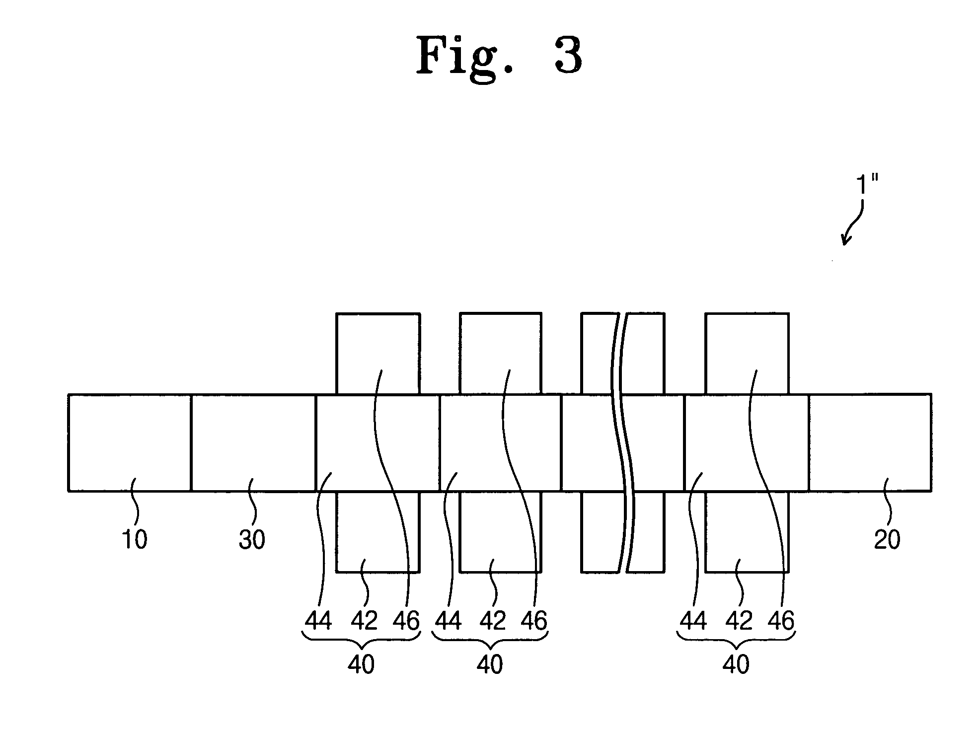
In a substrate processing apparatus for forming thin layers on a substrate used for an organic light emitting diode, the apparatus includes a mask attaching chamber, a deposition chamber and a mask detaching chamber. The mask attaching chamber, the deposition chamber and the mask detaching chamber are provided with a transferring guide installed thereinside, and a substrate supporter for supporting the substrate moves along the transferring guide in or between the chambers. Thus, a time for processing the substrate and an area for the apparatus may be reduced. Also, the chambers are grouped in one or more, and a gate valve is installed between the grouped chambers for opening and closing a path between the grouped chambers. Accordingly, the chambers may be continuously maintained in a vacuum state when any one of the chambers is repaired.

Description

CROSS-REFERENCE TO RELATED APPLICATION [0001] This application relies for priorities upon Korean Patent Applications No. 2005-11334 filed on Feb. 7, 2005, No. 2005-18240 filed on Mar. 4, 2005 and No. 2005-27022 filed on Mar. 31, 2005 the contents of which are herein incorporated by reference in their entireties. BACKGROUND OF THE INVENTION [0002] 1. Field of the Invention [0003] The present invention relates to an apparatus for processing a substrate. More particularly, the present invention relates to an apparatus for carrying out a process to form a thin film on a substrate applied to an organic light-emitting diode. [0004] 2. Description of the Related Art [0005] Recently, information processing devices are rapidly developed to have various shapes and functions with rapid data processing speed. Such information processing devices have a display device for displaying the processed information. As the display device, a cathode ray tube type display device was mainly used, but a fla...

Claims


Application Information

Patent Timeline
Patent Type & Authority Applications(United States)
IPC IPC(8): B05C11/02B05C11/11B05C11/00
CPCH01L21/67173H01L21/67236H01L21/67748
Inventor AN, KI-CHOULJOUNG, YOUNG-CHULHA, TAE-YOUNGCHANG, JUNG-WONNOH, IL-HOLEE, SEUNG-BAE
Owner SEMES CO LTD
Learn More