Piezoelectric vibrator, method for adjusting piezoelectric vibrator, piezoelectric actuator, timepiece, and electronic device

a piezoelectric actuator and piezoelectric technology, applied in the direction of piezoelectric/electrostrictive device details, device material selection, instruments, etc., can solve the problem that the characteristic frequency cannot be adjusted to the specified range, the q value and other such vibration characteristics may degrade, and the energy required is large, so as to achieve simple and reliable adjustment and excellent reliability

Inactive Publication Date: 2006-08-10
SEIKO EPSON CORP
View PDF3 Cites 16 Cited by
  • Summary
  • Abstract
  • Description
  • Claims
  • Application Information

AI Technical Summary

Benefits of technology

[0080] According to this invention, including the above-described piezoelectric vibrator makes it possible to achieve the same operations and effects as those previously described. Specifically, it is possible to provide an electronic device with excellent reliability because the characteristic frequencies of the piezoelectric vibrator are simply and reliably adjusted.
[0081] A piezoelectric vibrator can be provided by a simple method wherein an adjustment electrode for adjusting the area to which voltage is applied is provided in advance to part of the electrodes of the piezoelectric element, and either electricity is cut off between the adjustment electrode and a drive electrode to which voltage is applied, or the adjustment electrode is made conductive with the drive electrode to adjust the characteristic frequencies, whereby there is virtually no degradation in the vibration characteristics, the characteristic frequencies can be reliably adjusted with little nonuniformity in the adjusted amounts of the characteristic frequencies, and individual differences pertaining to the characteristic frequencies can be eliminated.

Problems solved by technology

However, with a method for varying the dimensions of the vibrator by cutting off pieces of the piezoelectric element as described in Prior Art 1, a large amount of energy is required, and the Q value and other such vibration characteristics may degrade due to the power or heat applied to the piezoelectric vibrator.
Furthermore, since many steps are required for adjustment and it is difficult to cut the material from the front side of the piezoelectric element irradiated with a laser beam to the reverse side with accurate dimensions, problems are encountered in which the characteristic frequency cannot necessarily be adjusted to the specified range and the amount of adjustment is nonuniform.
In Prior Art 3, problems are encountered with degradation in the vibration characteristics, increases in the cycle time, and nonuniformities in the adjusted amounts, similar to Prior Art 1. Particularly, it is difficult to drive the piezoelectric actuator in a stable manner because the characteristic frequencies of both longitudinal vibration and bending vibration must be maintained in order to obtain the desired elliptical trajectory, and the vibration characteristics are extremely nonuniform if the characteristic frequencies are even slightly nonuniform.
This nonuniformity in the vibration characteristics poses a crucial problem, particularly in vibrators for low output.
In the method in Prior Art 2, it is difficult to control the amount of paint ejected, and therefore the amounts of paint are nonuniform among different piezoelectric vibrators, and the adjustment results have so far been unsatisfactory.
Moreover, since the vibration characteristics may degrade with a greater amount of paint, problems have been encountered in that the amount of paint is limited and the characteristic frequencies can only be adjusted within an extremely small range.

Method used


Image

  • Piezoelectric vibrator, method for adjusting piezoelectric vibrator, piezoelectric actuator, timepiece, and electronic device
  • Piezoelectric vibrator, method for adjusting piezoelectric vibrator, piezoelectric actuator, timepiece, and electronic device
  • Piezoelectric vibrator, method for adjusting piezoelectric vibrator, piezoelectric actuator, timepiece, and electronic device

Examples


first embodiment

[0115] The first embodiment of the present invention will now be described with reference to the diagrams.

[0116] In the descriptions of the second and subsequent embodiments, components similar to those of the first embodiment described below are denoted by the same reference numerals, and descriptions thereof are omitted or simplified.

[0117] (1. Schematic Configuration of Timepiece)

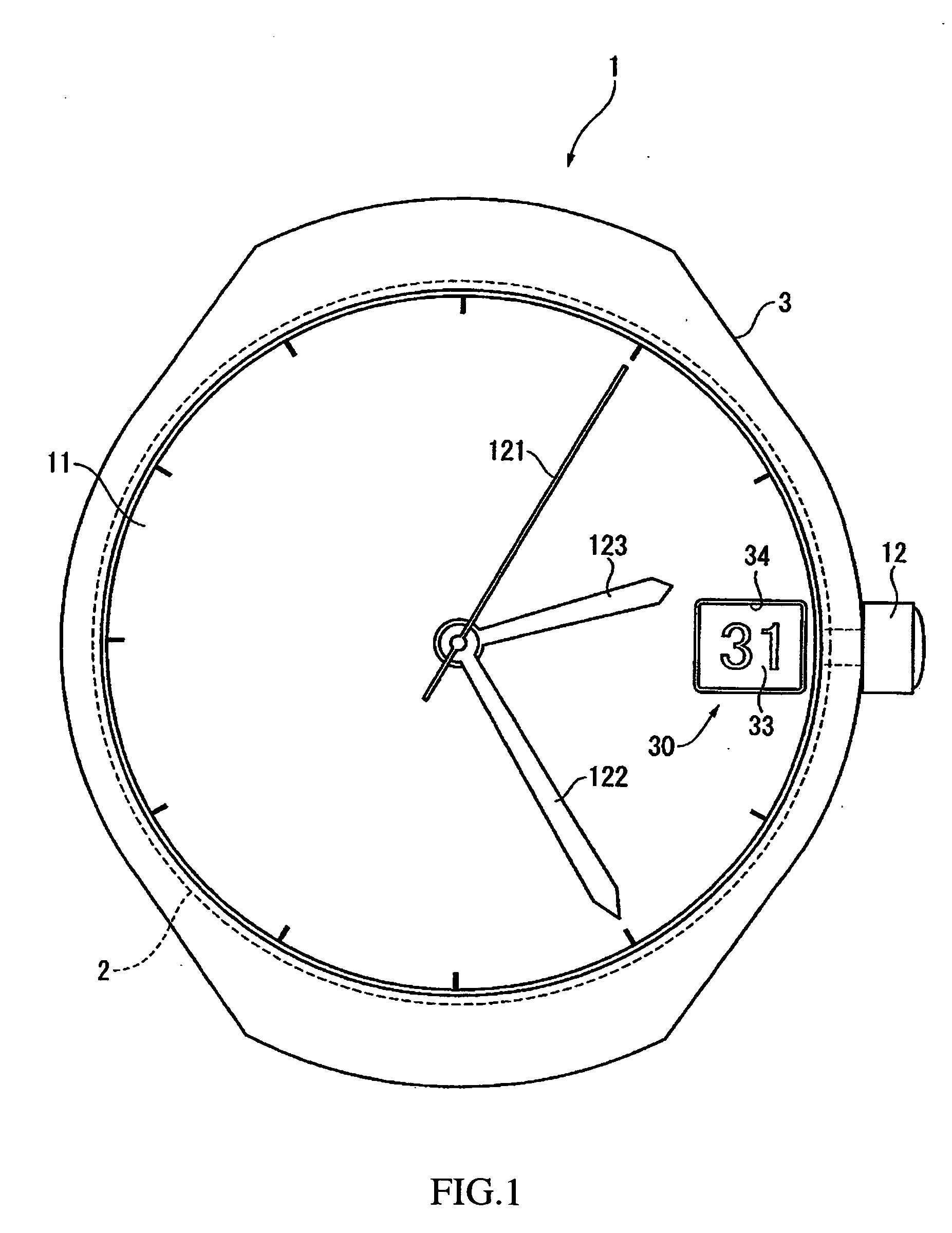
[0118]FIG. 1 is an external view of a timepiece 1 in the present embodiment.

[0119] The timepiece 1 is a wristwatch (watch) that includes a movement 2 as a drive device, and a case 3 for housing the movement 2. The type of this timepiece is an electronic timepiece (quartz), and the timepiece 1 of the present embodiment is configured as an analog quartz, with a dial 11 and a crown 12 mounted on the movement 2. A seconds hand 121, minute hand 122, and hour hand 123 are provided substantially in the middle of the dial 11. A substantially rectangular window 34 is provided in the 3:00 position of the dial ...

second embodiment

[0192] Next, the second embodiment in the present invention will be described.

[0193] The present embodiment differs from the first embodiment in that a plurality of adjustment electrodes are provided to the diagonal portions of the rectangle of the vibrator.

[0194]FIG. 9 is a plan view of a vibrator 70 in the present embodiment.

[0195] In the vibrator 70, the electrode 60 provided on the surface of the piezoelectric element is partitioned at the diagonal portions of the rectangle by linear grooves 75 and T-shaped grooves 76, and three adjustment electrodes 72 are formed at each diagonal portion.

[0196] Specifically, the linear grooves 75 extend from the two short sides of the vibrator 70 in the longitudinal direction to the middle of the vibrator 70 in the width direction.

[0197] Also, the T-shaped grooves 76 are aligned in sets of three extending from the ends of the vibrator 70 in the width direction along a direction orthogonal to the longitudinal direction near to the linear gr...

third embodiment

[0222] Next, the third embodiment of the present invention will be described.

[0223] In the present embodiment, unlike the first and second embodiments, the adjustment electrodes and the drive electrode are insulated in advance, and are also made conductive via a conductive member.

[0224]FIG. 14 is a plan view of a vibrator 80 in the present embodiment.

[0225] In the vibrator 80, the drive electrode 61 and the adjustment electrodes 82 are completely separated and mutually insulated in advance by grooves 85 and 86, and there are no conductive parts 73 from the previous embodiment. Specifically, the linear grooves 85 extend from the two short sides of the vibrator 80 in the longitudinal direction, three grooves 86 extend from the ends of the vibrator 80 in the width direction towards each of these grooves 85, and three adjustment electrodes 82 are aligned in the longitudinal direction of the vibrator 80 at both diagonal portions of the vibrator 80.

[0226] The present embodiment is sim...


PUM


Abstract

To provide, via a simple method, a piezoelectric vibrator wherein nonuniformities in the adjusted amounts of the characteristic frequencies are small, and the characteristic frequencies can be adjusted with little decrease in the vibration characteristics, whereby individual differences pertaining to the characteristic frequency can be eliminated.
In a vibrator 70, adjustment electrodes 72 are formed in advance on part of an electrode 60, and drive electrode 61 and adjustment electrodes 72 that have initially been made conductive relative to each other are electrically cut off and insulated from each other by cutting conductive parts 73, or the mutually insulated drive electrode 61 and adjustment electrodes 72 are made conductive (shorted) using solder, a wire, or another electrically conductive member, whereby the characteristic frequencies are adjusted simply and reliably. Individual differences in the vibrators 70 related to the resonance frequency (characteristic frequency) can thereby be eliminated, and reliability can be greatly improved.

Description

BACKGROUND OF THE INVENTION [0001] 1. Field of the Invention [0002] The present invention relates to a piezoelectric vibrator that vibrates due to the application of voltage to a piezoelectric element, a method for adjusting this piezoelectric vibrator, a piezoelectric actuator that includes this piezoelectric vibrator, a timepiece, and an electronic device. [0003] 2. Description of the Related Art [0004] In conventional practice, piezoelectric vibrators that use piezoelectric elements have been used in oscillators and actuators and the like in electronic circuits. In such piezoelectric vibrators, the characteristic frequency is determined by the characteristics and dimensions of the material, but the characteristic frequency in each individual vibrator must be adjusted because of the tendency of the characteristics of the piezoelectric material to be nonuniform, and because of the occurrence of errors in the working dimensions of the piezoelectric vibrators. [0005] One known method...

Claims


Application Information

Patent Timeline
Patent Type & Authority Applications(United States)
IPC IPC(8): H01L41/04G04C3/12H01L41/09H01L41/18H01L41/187H02N2/00
CPCG04C3/12G04C17/0058H01L41/0913H02N2/004H02N2/103H01L41/253H01L41/29H10N30/2023H10N30/04H10N30/06
Inventor SAWADA, AKIHIROSEKI, SHIGEAKIKAYAMORI, SUSUMU
Owner SEIKO EPSON CORP
Why Eureka
Try Eureka