Environmental control incubator with removable drawer and robot

a robot and incubator technology, applied in the field of environmental control incubators, can solve the problems of productivity limitation, reliability is the major problem that plagues, and the stated specifications are not always meaningful, and achieve the effect of final compactness of the system

Inactive Publication Date: 2006-08-10
AGILENT TECH INC
View PDF15 Cites 78 Cited by
  • Summary
  • Abstract
  • Description
  • Claims
  • Application Information

AI Technical Summary

Benefits of technology

[0006] Invention resides in the unique combination of a handling robot positioned between two rows of racks containing micro-titer plates or other containers useful for biological reactions. The advantages of this configuration are the ultimate compactness of the system with the invented incubator consuming unused volume in the lower half of a larger apparatus such as the Velocity11 BioCel®, the Thermo MultiScan Ascent, RTS Thurnall and others and the direct delivery of plates to positions within reach of the main robot, requiring no additional plate transfer step. Alternative embodiments standardize the spacing and configuration of a robot track and a shelf track such that a shelf and a robot are interchangeable in a track.
[0007] The invented incubator comprises an integrated environmental control unit (ECU) that delivers a stable environment of a predetermined gas composition, temperature and humidity protocol to a chamber with removable shelves containing racks that hold industry standard micro-titer plates. Alternative embodiments provide a controlled source of HEPA filtered gas, including ambient air or compositions containing predetermined mixtures of O2, CO2, N2 and others; alternatively programmable humidity selection is provided. An integrated, yet modular ECU, allows relocation to different positions for different product embodiments serving different applications. By minimizing plate access time, especially as it affects door-open time, and providing a robust climate control system, the invented incubator provides stable and reliable control over a broad range of potential protocols for the user.
[0008] The invented incubator further comprises a robot with servo motors with position encoding technology; computer programmable electronics enables simultaneous control of motion in multiple axes, ensuring reliable actuator operation and time-optimized robot trajectories, enabling quick access to plates with the least possible physical disturbance during plate transfer. Barcode reading components and processes combined with plate orientation sensing allow for real-time process verification. More complete characterization of error modes through improved, extended, and in some cases, redundant sensing enables superior fault handling.
[0009] In one embodiment the invented incubator is a subsystem of a larger robotic system such as a Velocity11 BioCel®, in this instance software is architected to provide for a primary system to issue commands and control an incubator subsystem, enabling greater flexibility for the customer. In one embodiment, firmware is written in C with an industry standard ActiveX communication protocol, exposing only the highest-level functions required to operate the device to the user. The software architecture combined with extensive data collection and inventory mapping enable fast and efficient plate management. More intelligent motion profiles and steps reduce process times for initializing and avoid superfluous moves such as reinitializing after a door has been opened or moving to park positions unnecessarily between steps, deficiencies of the prior art.

Problems solved by technology

Stated specifications are not always meaningful because the moves to which time values apply are not always clear.
Reliability is the major problem that plagues this market, especially with top-loading incubators.
The central carousel design of the Liconic cabinets hinders scaling to a larger number of racks; it also suffers from a productivity limitation in that only one robot can be engaged in the circular configuration of the racks, plates and robot.
The rack and pinion drive of the Liconic robot mechanism has difficulty placing micro-titer plates in a compactly designed plate holder rack due to its more complicated resolution limitations requiring additional gear boxes.
Additionally, (651) fails to teach how “automatic operation” is achieved without the use of positional sensors.
The other inventions disclosed suffer from comparable deficiencies; one example is lack of positional knowledge of a micro-titer plate when in motion, compromising the apparatus' ability to move quickly and with minimum motions to its destination; one solution of this problem in the prior art is the requirement to return to a home position prior to completing an instruction.
For instance, U.S. 2004 / 0152188 has not the ability to turn its micro-plate transport device in an angular motion; additionally it uses a chain drive, not conducive to vibration free motion or precise positioning.
These apparatus are insufficient for today's needs of high throughput screening of massive numbers of samples as required in combinatorial protocols for biological assays or microbiological incubations.

Method used


Image

  • Environmental control incubator with removable drawer and robot
  • Environmental control incubator with removable drawer and robot
  • Environmental control incubator with removable drawer and robot

Examples


Embodiment Construction

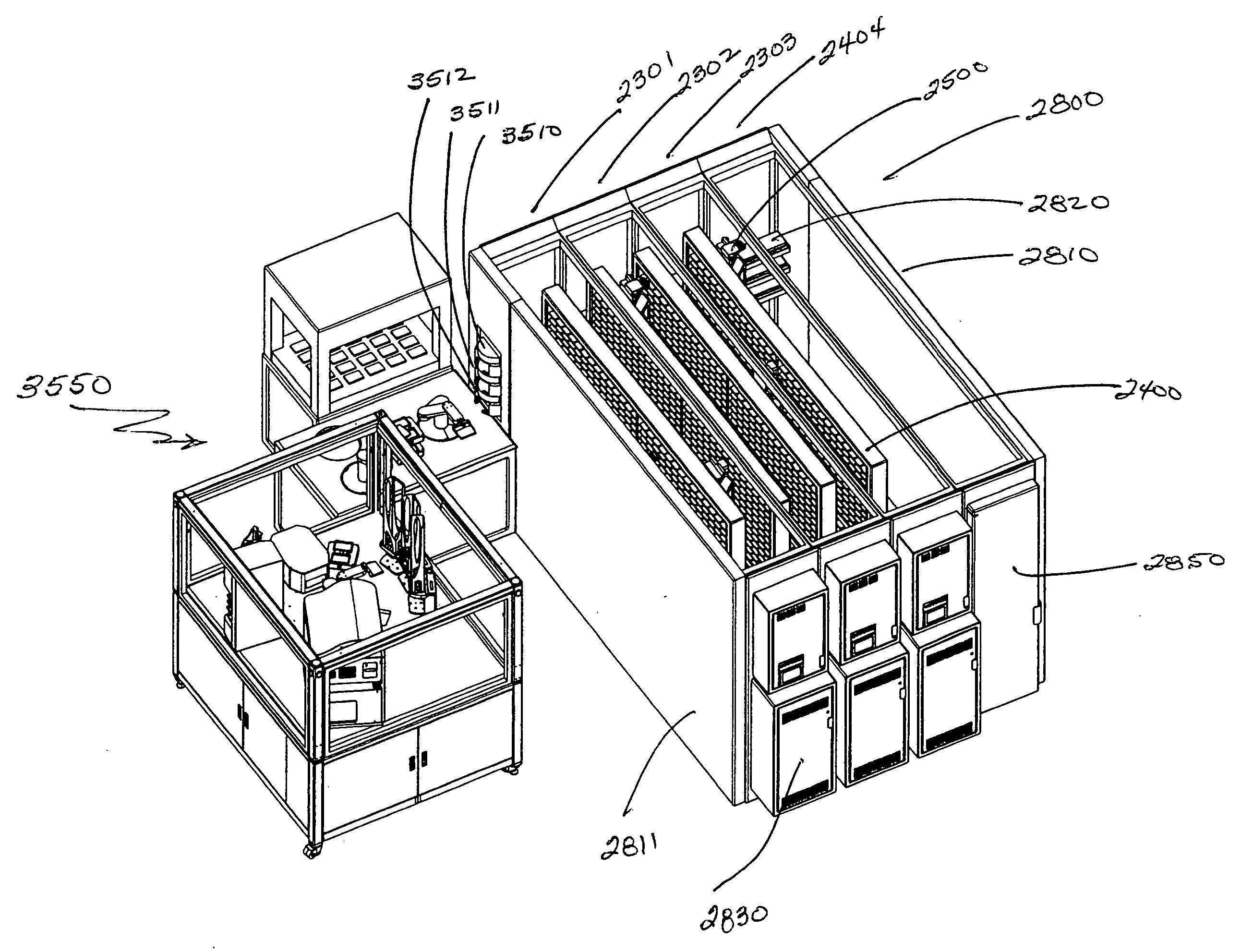
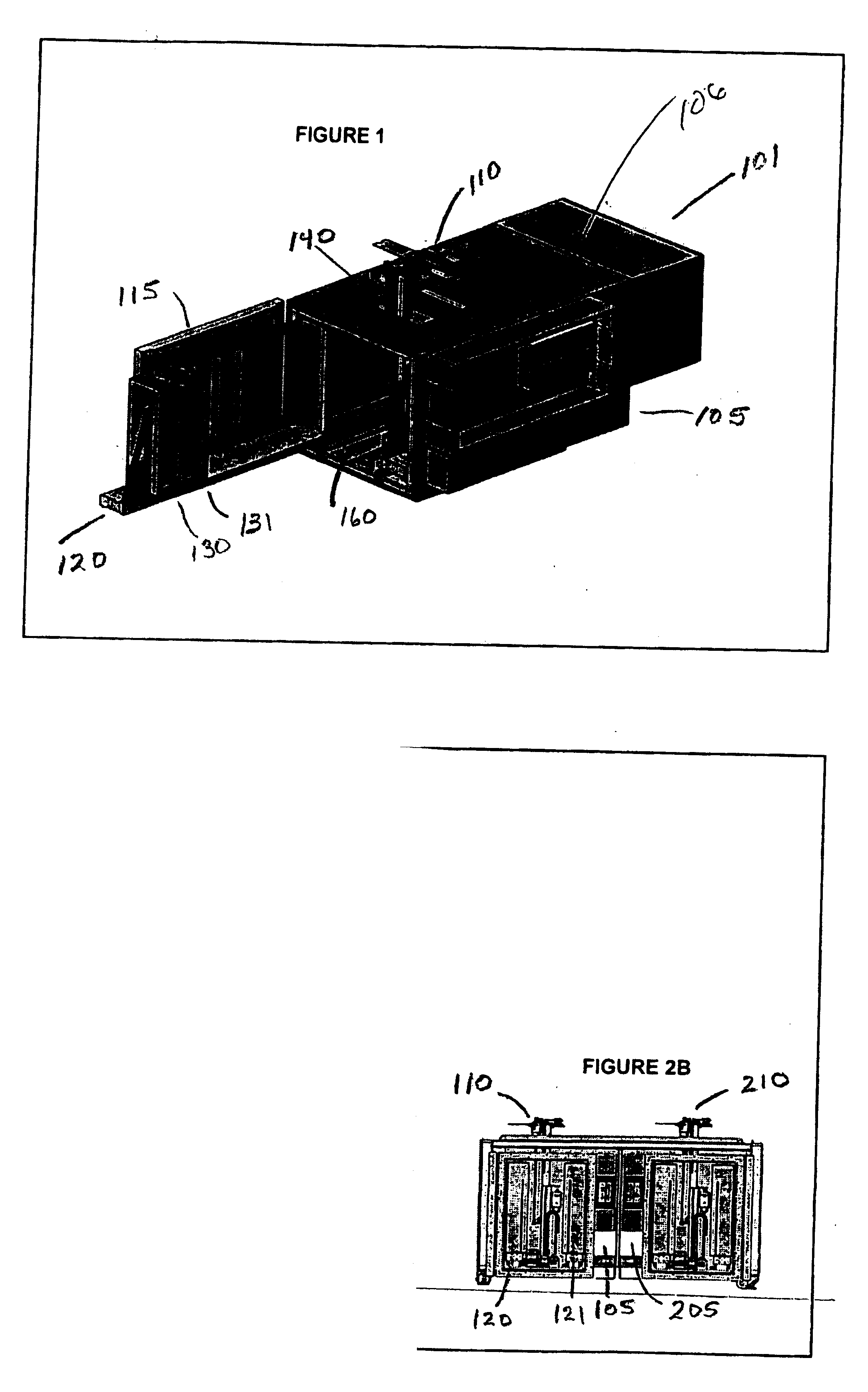
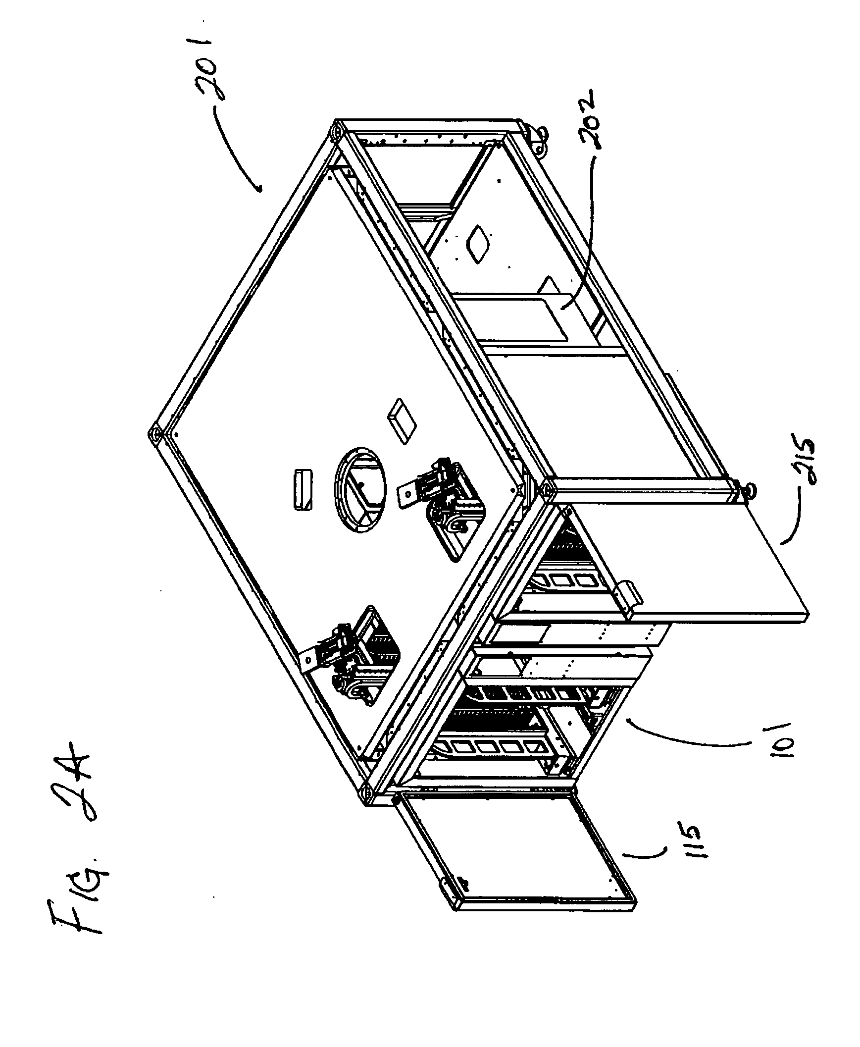
[0048]FIG. 1 shows incubator 101, electronics enclosure 105, extended robot 110, door 115, sliding shelf 120 and plate racks 130 and 131, second door 140, open, and base plate 160 to which two shelves, 120 and 121 (not shown) and five axis robot 110 are attached. FIGS. 2A and 2B are perspective and front views of two incubators 101 and 202 mounted in a mirror image arrangement 201, showing electronics 105 and 205 mounted on the interior surface, extended robots 110 and 210, doors 115 and 215. FIG. 3 is a higher detail drawing of incubator 101 with shelf 120 in the open position showing rack 130 with rack interface 340. FIG. 4 is a drawing of an incubator bottom portion showing construction details of two shelves 120 and 421 and lower robot detail 410. FIG. 5 is a detail drawing of an incubator shelf 120 showing space for up to seven racks such as 130. A handle 550 is configured as a support element for the shelf and racks. FIG. 6 is a detail drawing of an incubator rack 130 showing ...


PUM

PropertyMeasurementUnit
temperaturesaaaaaaaaaa
volumeaaaaaaaaaa
angleaaaaaaaaaa

Abstract

An incubator for storing micro-plates or micro-tubes comprises a handling robot positioned between shelves or drawers containing micro-titer plates or other containers useful for biological based reactions. The advantages of this configuration are the ultimate compactness of the system and increased speed or reliability achieved with more than one robot being able to access the same plate or tube. Alternative embodiments standardize the spacing and configuration of a robot track and a shelf track such that a shelf and a robot are interchangeable in a track.

Description

FIELD OF INVENTION [0001] Invention relates to an environmentally controlled chamber which promotes biologically based reactions on multiple plates under predetermined conditions with robotic placement and retrieval of the reaction plates. BACKGROUND OF INVENTION [0002] Cabinets of special construction for biological process investigation first appeared in the 1920's as microbiological incubators manufactured by the forerunner of Heraeus Instruments. Today incubators are used to store plates for a certain time at prescribed environmental conditions. In cell-based assay protocol, media and cells are added to empty plates that are then placed in the incubator to grow overnight. Typical environmental specs are 37° C. at 95% relative humidity with a 5% CO2 environment. During the following day plates are removed to add assay material and then replaced, being removed again later that day for reading. Temperature stability requirements depend on throughput but are typically about ±1° C. S...

Claims


Application Information

Patent Timeline
Patent Type & Authority Applications(United States)
IPC IPC(8): C12M1/34C12M1/36
CPCB01L7/00B01L9/523B01L2300/0829B01L2300/10C12M37/00G01N35/0099G01N35/028G01N2035/00356G01N2035/0498
Inventor SHAMAH, BENJAMIN NATHANROLLINS, ERIC JAMESSANDLER, REUBENMISTRY, NILESH CHHAGANLALMATSUMOTO, DAVID K.POWELL, RYANSMITH, THOMAS LAWRENCEBEVIRT, JOEBENBERMAN, RUSSELL T.YATES, IAN
Owner AGILENT TECH INC
Why Eureka
Try Eureka