Intravascular imaging detector

a detector and intravascular technology, applied in the field of intravascular imaging detectors, can solve the problems of not providing information about plaque content, and achieve the effects of maximizing passive properties, high degree of safety, and high degree of safety

Inactive Publication Date: 2006-08-10
CMR NAVISCAN CORP +1
View PDF58 Cites 10 Cited by
  • Summary
  • Abstract
  • Description
  • Claims
  • Application Information

AI Technical Summary

Benefits of technology

[0027] The apparatus of the present invention preferably provides both high beta particle detection efficiency and sufficient sensitivity in the very small detector volume afforded by an intravascular or other medical catheter tip.
[0030] The apparatus of the present invention allows for high efficiency for betas and very low detection efficiency for 511 keV gammas. Generally we have precluded materials that have either high atomic number or high density. Gasses, liquids, light plastics and thin low-Z semiconductors have been found to be preferable in this respect to high Z compound semiconductors.
[0034] The apparatus of the present invention allows construction to maximize its passive properties, which are attractive due to the higher degree of safety during procedures. The preference had been given to detectors composed of inert materials due to the higher degree of safety during procedures.
[0035] The detection mechanisms of the apparatus of the present invention allow for the highest signal and sensitivity of the detector. This criterion favors the semiconductor detector approach, which offers the most efficient energy transfer.
[0036] The apparatus of the present invention allows for a construction that can be integrated with the catheter and guidewire.

Problems solved by technology

Angiography however, cannot provide information about plaque content.

Method used


Image

  • Intravascular imaging detector
  • Intravascular imaging detector
  • Intravascular imaging detector

Examples


Embodiment Construction

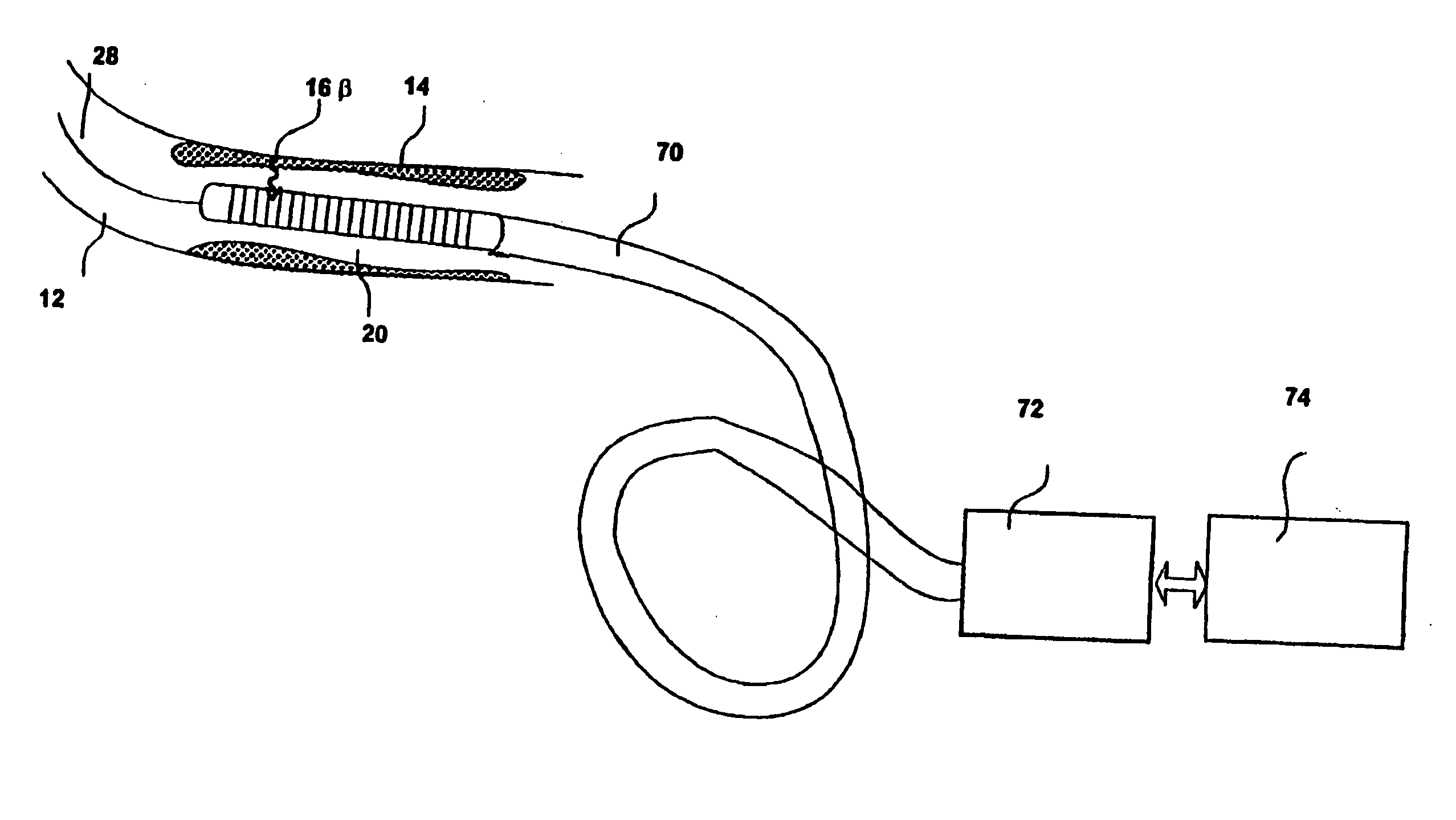
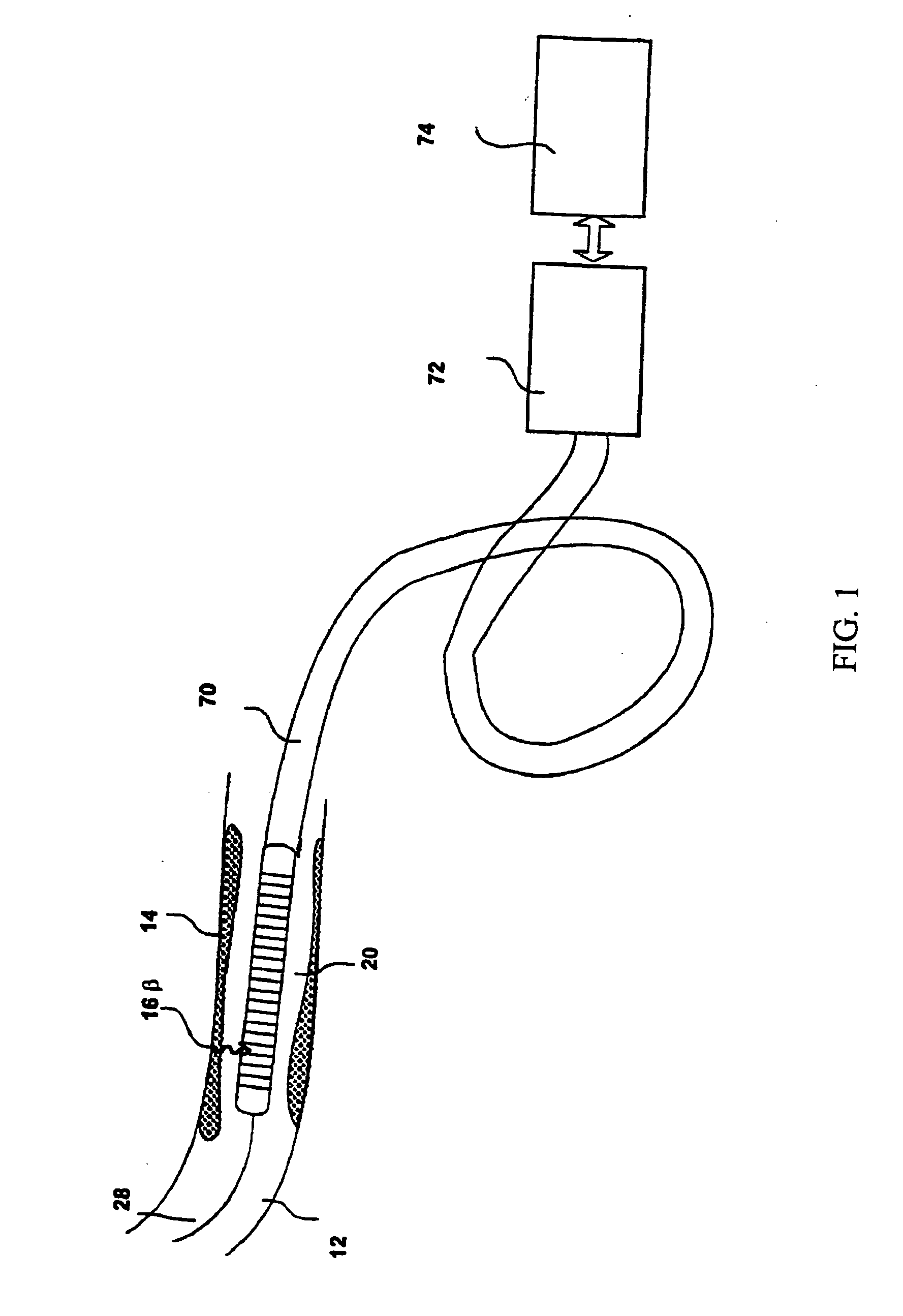
[0057] Referring to FIG. 1 an apparatus for imaging in arteries 12 to detect and characterize early-stage, unstable coronary artery plaques 14 is comprised of an imaging probe tip 20 which includes a miniature beta sensitive detector. It works by identifying and localizing plaque-binding radiopharmaceuticals that emit beta particles 16. The radiation detector has an intrinsic spatial resolution of approximately 1-3 mm. It is integrated into an arterial catheter 70 so that it can be manipulated through the artery by a guidewire 28 in much the same way as a balloon catheter for angioplasty. The detector of the present invention once integrated into the catheter 70 connects to data acquisition electronics 72 and a computer and display 74, which provides an image of the distribution of plaque.

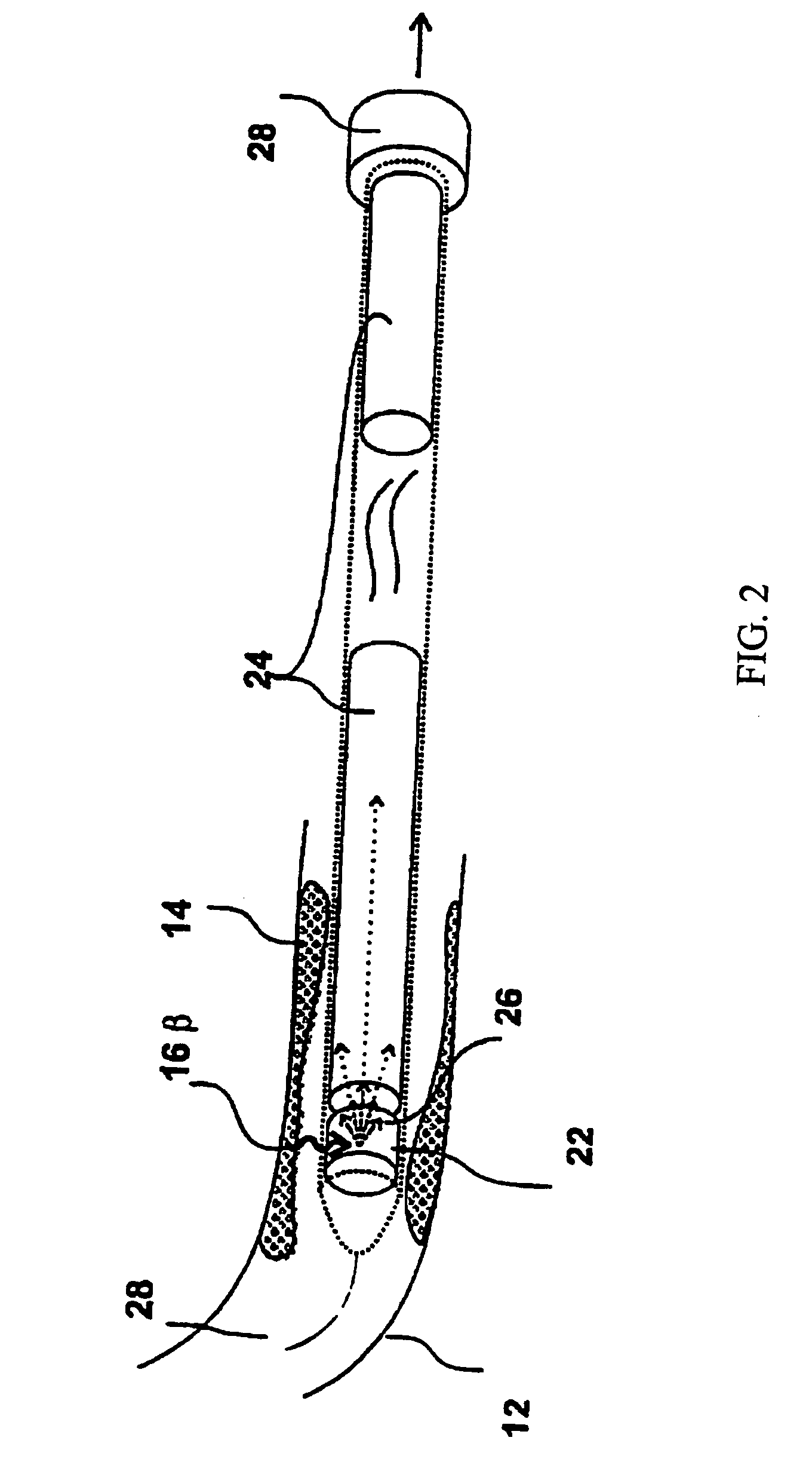
[0058] A specific embodiment of the intravascular imaging probe tip 20 constructed in accordance with the principles of the present invention is comprised of a scintillating fiber 22 coupled to a ...


PUM


Abstract

An apparatus for intravascular imaging to detect and characterize early stage, unstable coronary arty plaques. The detector works by identifying and localizing plaque-binding beta-emitting radiopharmaceuticals.

Description

CROSS-REFERENCE TO RELATED APPLICATION(S) [0001] The present application is a divisional of U.S. patent application Ser. No. 09 / 754,103, filed Jan. 3, 2001, which claims benefit under 37 C.F.R. §1.78 of U.S. Provisional Application No. 60 / 174,440, filed Jan. 4, 2000, and entitled “Intravascular Imaging Detector,” the entire contents of both of which are incorporated by reference herein. The present application also incorporates U.S. Pat. No. 6,782,289, issued on Aug. 24, 2004, by reference herein.BACKGROUND OF THE INVENTION [0002] Coronary angiography is used to identify and measure the luminal dimensions of blood vessels. Angiography however, cannot provide information about plaque content. [0003] The subject invention addresses this deficiency by placing an imaging detector into the arteries to detect and characterize early-stage, unstable coronary artery plaques. This can provide a signature relevant to the 70% of heart attacks that are caused by minimally obstructive, unstable p...

Claims


Application Information

Patent Timeline
Patent Type & Authority Applications(United States)
IPC IPC(8): A61B5/05A61B6/00G01T1/164G01T1/161G01T1/20
CPCA61B6/4057A61B6/425A61B6/4258G01T1/161
Inventor IWANCZYK, JAN S.PATT, BRADLEY E.HOFFMAN, EDWARD J.
Owner CMR NAVISCAN CORP
Why Eureka
Try Eureka