Photoreceptive layer comprising metal oxide of core-shell structure and solar cell using the same

a solar cell and metal oxide technology, applied in the field of photoacceptive layer, can solve the problems of difficult electron migration to a central core through an outer shell, limited practical use and cell efficiency of solar cells, etc., and achieve the effect of preventing a recombination reaction and improving photoconversion efficiency

Inactive Publication Date: 2006-08-17
SAMSUNG ELECTRONICS CO LTD +1
View PDF6 Cites 14 Cited by
  • Summary
  • Abstract
  • Description
  • Claims
  • Application Information

AI Technical Summary

Benefits of technology

[0013] The present invention may provide a photoacceptive layer which prevents a recombination reaction and has improved photoconversion efficiency.

Problems solved by technology

However, such a Si solar cell is limited in practical use and cell efficiency due to its high manufacturing costs.
However, the largest problem in this instance is that since different oxides are used to form the core-shell structure, interfacial resistance increases, which makes it difficult for electrons to migrate to a central core through an outer shell.
That is, since a conventional oxide layer includes core particles having a protective layer (shell) formed thereon as illustrated in FIG. 2, electrons produced from dye molecules must migrate to a transparent conductive substrate through a shell, a core, a shell, a core, etc., and thus electron migration is difficult due to interfacial resistance generated when electrons migrate through interfaces.
As a result, the protective layer cannot prevent the recombination reaction.

Method used


Image

  • Photoreceptive layer comprising metal oxide of core-shell structure and solar cell using the same
  • Photoreceptive layer comprising metal oxide of core-shell structure and solar cell using the same
  • Photoreceptive layer comprising metal oxide of core-shell structure and solar cell using the same

Examples


example 1

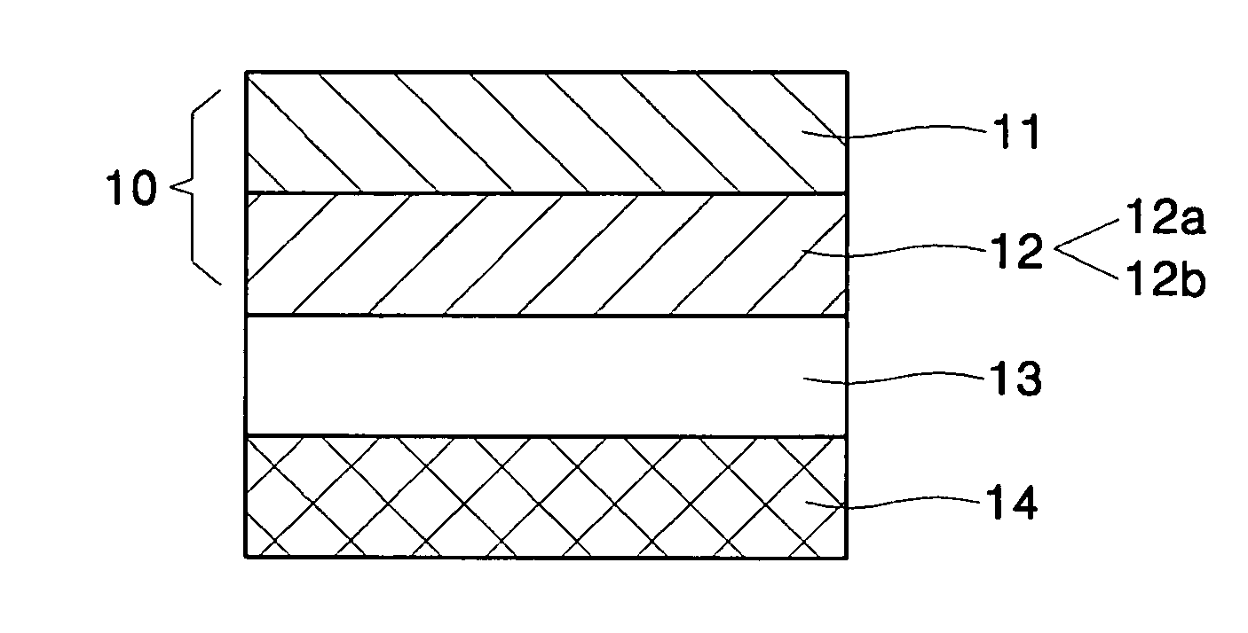
[0046] A TiO2 paste (available from Solaronix, TI nanoxide, HTSP) was coated on a transparent conductive glass substrate coated with ITO and having a transmittance of 80% to a size of 1×1 cm2. The coated glass substrate was subjected to a thermal treatment process at 450° C. for 30 minutes. During this time, the thermal treatment conditions were a heating rate of 3° C. / min and a cooling rate of 5° C. / min.

[0047] 5 wt % Tyzor (available from Dupont) was used to form a shell structure on the thermally treated sample. The 5 wt % Tyzor was prepared by adding 47.5 g of butanol to 2.5 g of Tyzor.

[0048] To form the shell structure on the TiO2 layer of a core structure, the 5 wt % Tyzor solution was coated on the TiO2 layer by dipping, and was then subjected to a thermal treatment process in an oven at 100° C. for 20 minutes. The immersion time was 30 seconds.

[0049] The resultant photoelectrode was immersed in a dye (available from Solaronix, Ru 535) for 20 hours to allow the dye to be ad...

example 2

[0050] A dye-sensitized solar cell was manufactured in the same manner as in Example 1, except that a sample coated with TiO2 was immersed in the 5 wt % Tyzor solution for 60 seconds by dipping.

experimental example

[0052] Photocurrent voltages of the dye-sensitized solar cells manufactured in Examples 1 and 2 and Comparative Example 1 were measured using a photocurrent measurement system (e.g. Solar simulator available from Seric, I-V Curve Tracer available from Eko) to obtain a photocurrent voltage curve. A current density (Isc), a voltage(Voc), and a fill factor (FF) were calculated from the photocurrent voltage curve. Then, the photoconversion efficiency (ηe) was obtained from the calculated values and shown in Table 1. The photoconversion efficiency is calculated using the following equation:

ηe=(VocIscFF) / (Pinc)

[0053] where Pinc is 100 mw / cm2 (1 sun).

TABLE 1FF (%)Photoconversion efficiency (%)Example 157.54.170Example 256.73.982Comparative Example 154.83.964

[0054] As is apparent from Table 1, the dye-sensitized solar cells having the photoacceptive layer according to the present invention had improved FF, and thereby, an improved photoconversion efficiency compared to the dye-sensitize...


PUM

PropertyMeasurementUnit
thicknessaaaaaaaaaa
thicknessaaaaaaaaaa
thicknessaaaaaaaaaa

Abstract

A photoacceptive layer having a core-shell structure and a solar cell using the same are provided. More specifically, a photoacceptive layer including a metal oxide of a core-shell structure which can improve photoconversion efficiency by improving a electron migration path, and a solar cell using the same are provided.

Description

CROSS-REFERENCE TO RELATED PATENT APPLICATION [0001] This application claims priority from Korean Patent Application No. 10-2005-0006349, filed on Jan. 24, 2005, in the Korean Intellectual Property Office, the disclosure of which is incorporated herein in its entirety by reference. BACKGROUND OF THE DISCLOSURE [0002] 1. Field of the Disclosure [0003] The present disclosure relates to a photoacceptive layer comprising a metal oxide of a core-shell structure and a solar cell using the same, and more particularly, to a photoacceptive layer comprising a metal oxide of a core-shell structure which can improve photoconversion efficiency by improving a electron migration path, and a solar cell using the same. [0004] 2. Description of the Related Art [0005] To address currently occurring energy problems, studies on alternatives to conventional fossil fuels have been conducted. In particular, broad studies on the utilization of natural energy such as wind power, atomic energy, and solar powe...

Claims


Application Information

Patent Timeline
Patent Type & Authority Applications(United States)
IPC IPC(8): H02N6/00
CPCH01G9/2027H01G9/2031Y02E10/542Y02E60/13Y02P70/50G01N21/31G01N2030/009
Inventor PARK, SANG-CHEOLNAM, JUNG-GYUSONG, KI-YONGNOH, CHANG-HO
Owner SAMSUNG ELECTRONICS CO LTD
Why Eureka
Try Eureka