Compact hoist for drilling or workover rig

a hoist system and compact technology, applied in the field of hoist systems, can solve the problems of high pressure design, impair the maximum vertical lift capacity of the prior art hoist system, impair the horizontal range of motion and maximum vertical lift capacity etc., to improve the vertical and horizontal range of operation of the hoist system, improve the hoist speed and versatility, and eliminate chain failures

Inactive Publication Date: 2006-08-17
KEPPEL JAMES R
View PDF14 Cites 41 Cited by
  • Summary
  • Abstract
  • Description
  • Claims
  • Application Information

AI Technical Summary

Benefits of technology

[0018] The present invention provides an improved hoist system for use on a rig that utilizes wire rope instead of chain and that eliminates chain failures, improves hoist speed and versatility, and expands the vertical and horizontal range of operation of the hoist system. Expanding the range of operation increases usable rig storage space and allows handling of larger BOP stacks as compared to chain hoists.
[0019] The present invention overcomes several shortcomings resulting from the use of chain hoists for transferring BOP stacks on a rig. The present invention enables the unloading of the trolley used to position the block over the load.
[0020] Where the chain used in a chain hoist is stored in and retrieved from a chain bucket that is secured to a moving trolley, the present invention provides a grooved drum that is operatively aligned with, but not secured to, the trolley for storage of the wire rope used in the hoist. Where tension in the chain to operate a chain hoist is provided by a chain pocket wheel and a gearbox that are secured to the trolley, the present invention provides tension to the wire rope using a winch comprised of a grooved drum with drive system. The drum and drive system combination are slidably mounted on a stationary base that allows the drum to move along its axis of rotation in a manner that provides uniform winding of the wire rope within a spiral groove on the circumference of the drum and that maintains the pathway of the wire rope aligned with the receiving sheave on the moving trolley.

Problems solved by technology

Annular preventers can typically be closed around a range of tubular sizes or over an open hole, but are generally not designed to contain high pressures that can be more effectively contained by ram-type preventers.
The presence of the drive system, gearbox, chain pocket wheel and chain bucket onboard and moving with the trolley impairs the horizontal range of motion and the maximum vertical lift capacity of the prior art hoist systems.
Since the prior art hoist systems position the chain pocket wheel directly over the load, the winch must be physically disposed between the movable trolley and the lifting block, thereby impairing the maximum vertical lift capacity of the hoist system.
The bulky arrangement of the multiple gears in the gear box, the drive system and the chain bucket on the trolley impairs the horizontal range of motion and related lift zone of the prior art chain hoist system.
Chain pocket wheels will malfunction if operated at medium angular velocities, and any deviation from vertical in the chain feed as it engages the chain pocket may also result in malfunction.
Another problem with chain hoist systems for handling BOP stacks is that the interaction of a chain link with the adjacent chain link causes metallurgical deformation that may lead to catastrophic failure of the chain hoist.
This forcible disalignment of adjacent chain links while under load causes undesirable sliding contact, localized surface wear and possible cracking in the “U” portion of the chain links.
In an offshore marine environment, surface cracking may result in catastrophic chain failure due to stress corrosion cracking or some other mode of corrosive or mechanical failure.
Although wire rope has a superior load bearing capacity as compared to an equal weight of chain, wire rope cannot be easily gripped or pulled in short lengths.
The difficulty in adapting large wire rope storage drums for use on moving trolleys has prevented their use in hoist systems that handle BOP stacks on rigs.
Since the winch is positioned vertically between the trolley and the block, the increased BOP stack height impairs the maximum height to which the block can be raised on a chain hoist.
If the top of the BOP stack is above or even with the block when raised to its maximum vertical height, the hoist system cannot safely lift the BOP stack to or from the stump.

Method used


Image

  • Compact hoist for drilling or workover rig
  • Compact hoist for drilling or workover rig
  • Compact hoist for drilling or workover rig

Examples


Embodiment Construction

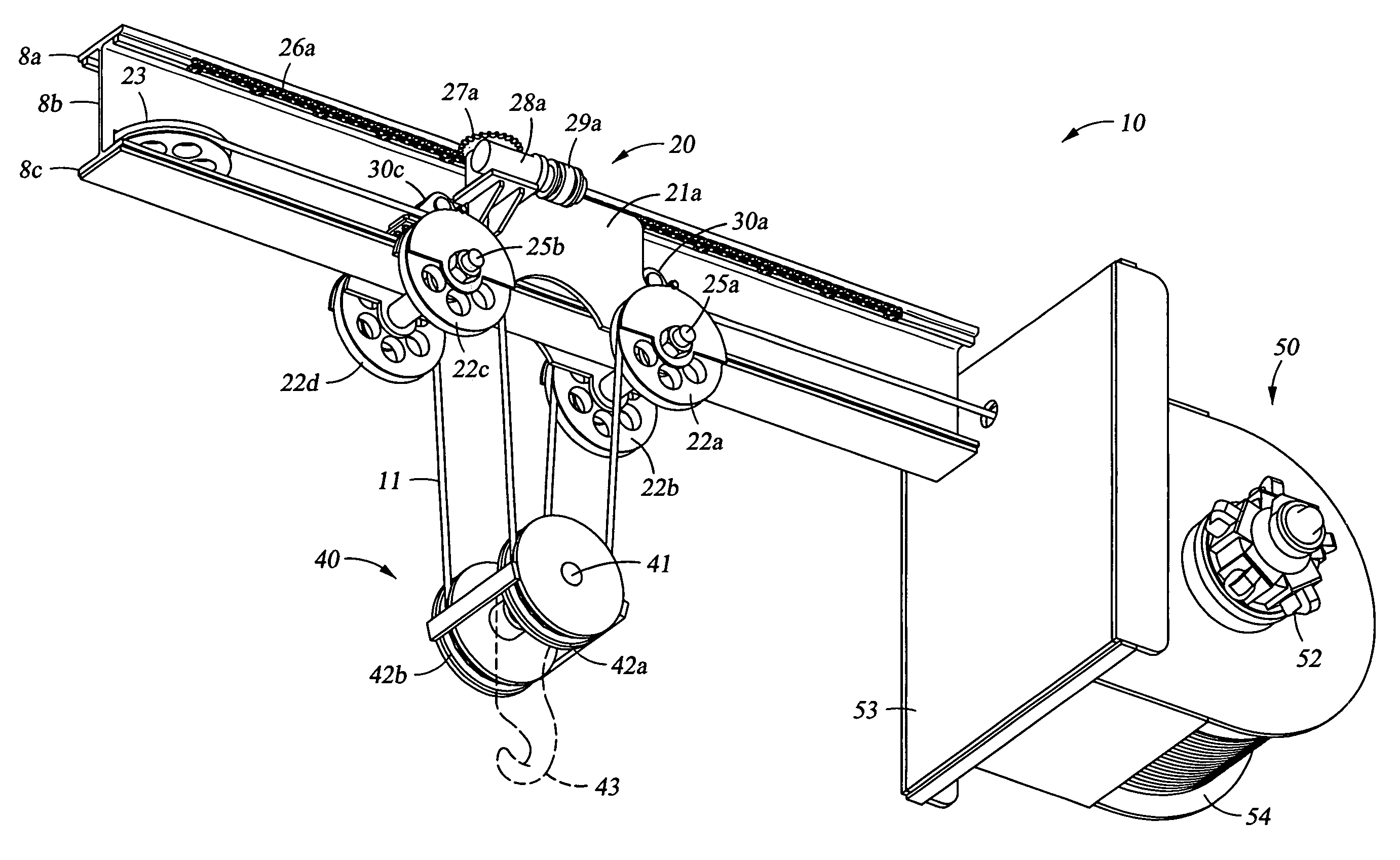
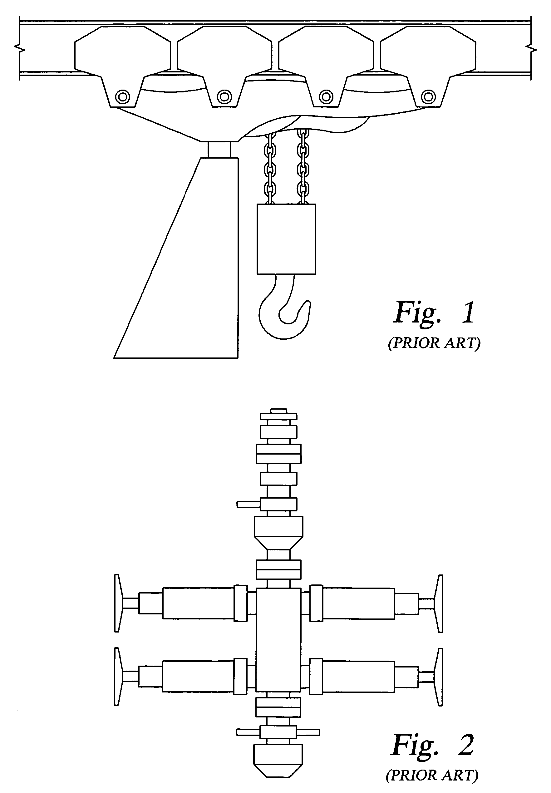
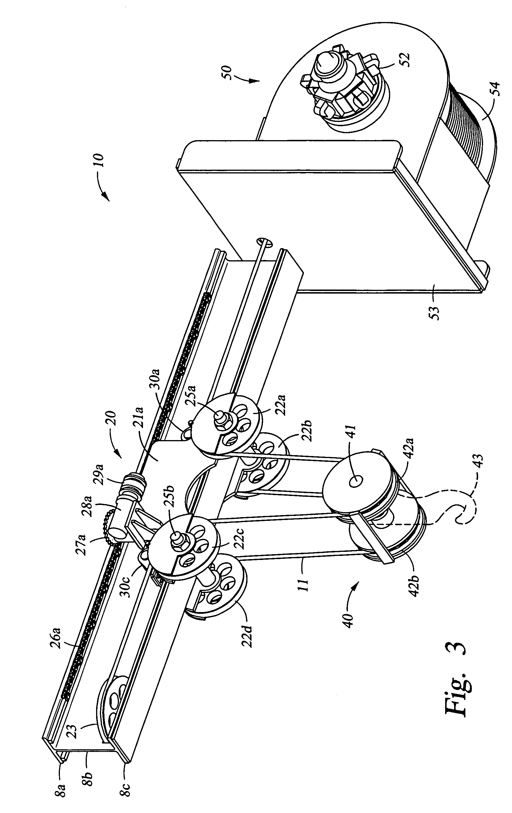
[0045] The present invention provides a hoist system and methods for its use that are useful for lifting and positioning equipment, such as BOPs, on an oil or gas well rig. For purposes of using the drawings to support the disclosure herein, it is required that terminology for referring to various similar or identical components of the invention be defined. In referring to the above-reference drawings, “proximal” is used to refer to components or portions of components disposed nearer to the grooved drum, and “distal” is used to refer to components or portions of components disposed nearer to the equalizing sheave that is opposite the grooved drum relative to the trolley portion. “Front” is used to refer to components or portions of components in the foreground of the above-referenced drawings relative to the I-beam center portion along which the trolley portion travels, and “rear” is used to refer to those components or portions of components on the opposite side of the I-beam cent...


PUM


Abstract

The present invention provides a compact hoist system for use on a drilling or workover rig. The present invention eliminates problems related to chain failures in hoist systems by incorporating wire rope in a vertically and horizontally compacted arrangement to provide maximum vertical lift capacity and improved versatility. Caterpillar bearings, wire rope tension equalizing sheaves and a winch coupled to a axially movable spiral-grooved drum are combined to provide a system that enables cantilever jack-up rigs to handle blow-out preventer stacks of increased height and size.

Description

BACKGROUND OF THE INVENTION [0001] 1. Field of the Invention [0002] The present invention relates to a hoist system for use on a drilling or workover rig. Specifically, the present invention relates to a vertically and horizontally compact hoist system having an expanded range of motion, improved maneuverability, faster operation and improved safety. [0003] 2. Description of the Related Art [0004] Drilling rigs are versatile because they can be utilized both for the offshore drilling of new wells and for workovers on existing offshore wells. These drilling and workover rigs require robust hoist systems for transferring equipment or materials to or from the wellhead. [0005] An important piece of equipment handled by hoist systems on a rig is the blowout preventer stack. Blow-out preventers (BOPs) are devices that are secured to a wellhead to enable rapid isolation and containment of the well in the event of a well control problem. A BOP is essentially a large valve installed at the t...

Claims


Application Information

Patent Timeline
Patent Type & Authority Applications(United States)
IPC IPC(8): B66C19/00
CPCB66C9/08B66C11/20
Inventor KEPPEL, JAMES R.
Owner KEPPEL JAMES R
Why Eureka
Try Eureka