Semiconductor device

a technology of semiconductor chips and electrode pads, applied in the direction of valves, oxygen/ozone/oxide/hydroxide, mechanical devices, etc., can solve the problem that the size of electrode pads is difficult to be reduced in comparison, and achieve the effect of enlarge the wiring area and not increase the area of semiconductor chips

Active Publication Date: 2006-08-17
SYNAPTICS JAPAN GK
View PDF7 Cites 28 Cited by
  • Summary
  • Abstract
  • Description
  • Claims
  • Application Information

AI Technical Summary

Benefits of technology

[0012] It is an object of the present invention to provide a technique which can enlarge a wiring region on a main surface of a semiconductor chip, particularly a signal wiring region in a semiconductor chip main surface of an LCD driver, without increasing the chip area.
[0017] It is possible to enlarge the wiring area on a main surface of a semiconductor chip without increasing the area of the semiconductor chip.

Problems solved by technology

However, as noted above, the size of an electrode pad is difficult to be reduced in comparison with the size of a semiconductor element and that of wiring.

Method used


Image

  • Semiconductor device
  • Semiconductor device
  • Semiconductor device

Examples


first embodiment

[0061] With reference to FIGS. 1 to 11, a description will be given below about a semiconductor device according to a first embodiment of the present invention applied to an LCD driver for which the reduction of the area of a semiconductor chip and a multi-output structure are required.

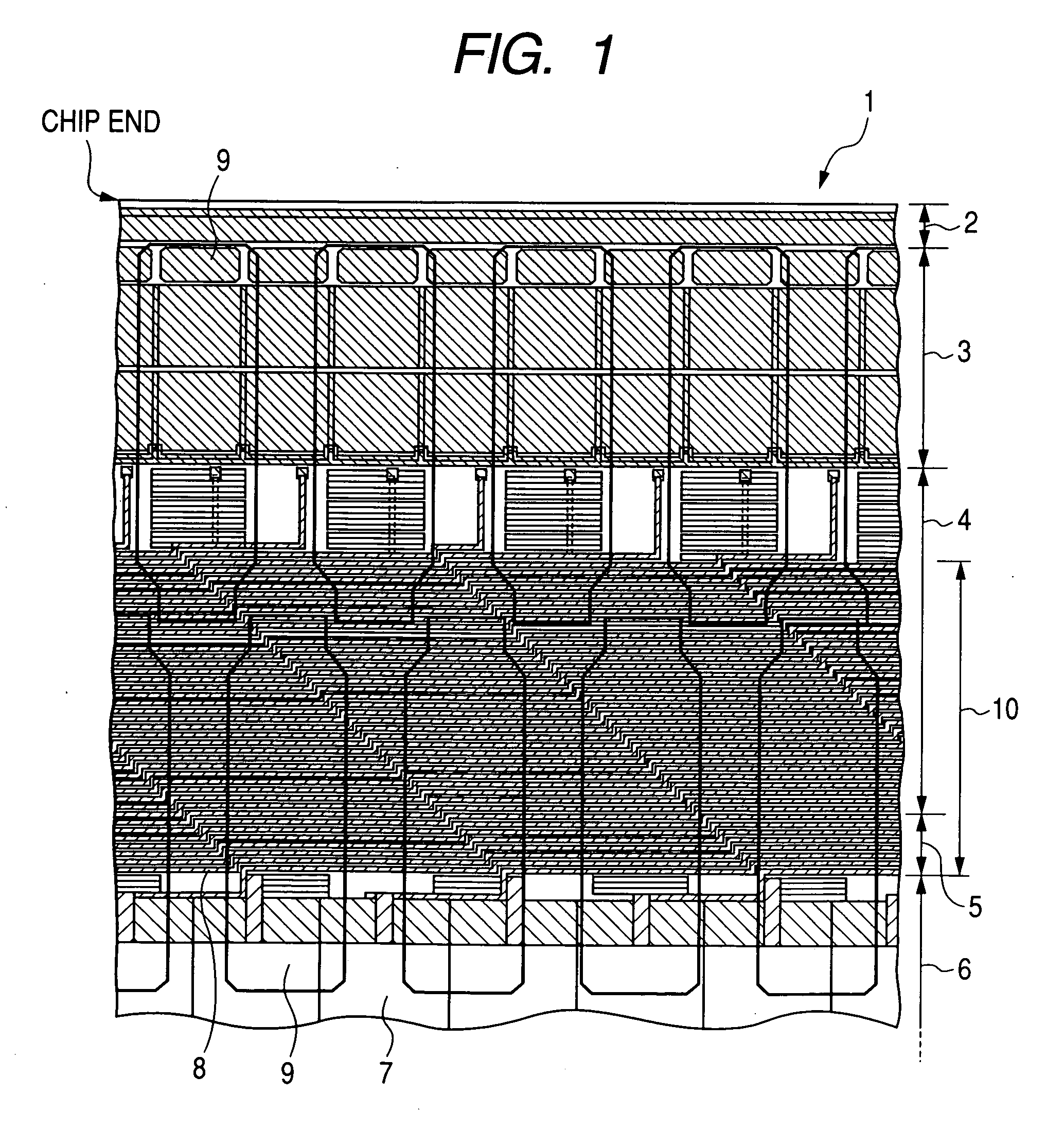
[0062]FIG. 1 is a plan view showing schematically a principal portion of the semiconductor device indicated at 1. Electrode pads 9 are also shown in the same figure in a see-through state.

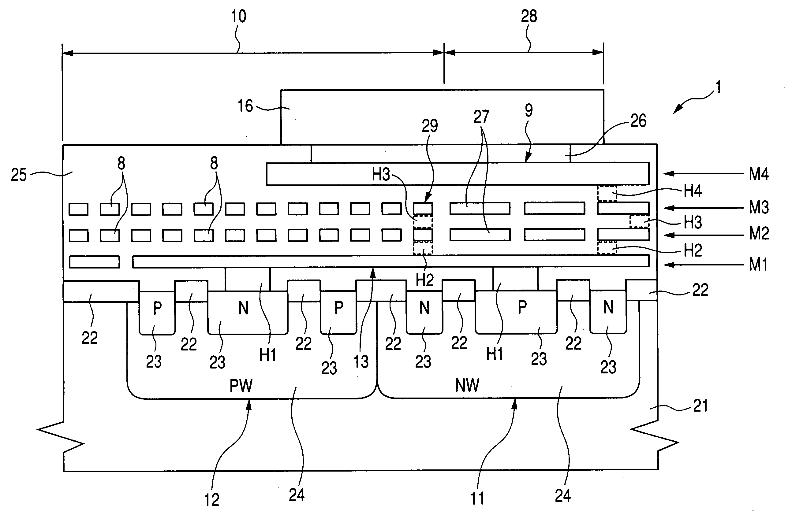
[0063] On a main surface of a semiconductor chip of the semiconductor device 1, a scribe region 2, element region 3, element region 4, element isolation region 5 and element region 6 are arranged in this order from a chip end side toward a chip center side (in the vertical direction in FIG. 1).

[0064] The element region 6 is a region in which is formed an internal circuit 7 including, for example, MIS transistor and diodes. The element isolation region 5 is a region in which is formed, for example, LOCOS (local oxi...

second embodiment

[0105] In the previous first embodiment, as shown in FIG. 2, the outlet ports 29 for the signal lines 8 are provided between the protective elements 11 and 12 in the semiconductor device having electrode pads 9 arranged in zigzags in two rows along a chip end side. In this second embodiment, a description will be given about a semiconductor device wherein outlet ports for the signal lines 8 are formed on a chip end side.

[0106]FIG. 12 is a plan view showing schematically a connection of principal portions in the semiconductor device according to this second embodiment, in which electrode pads 9 are shown in a see-through state.

[0107] As shown in FIG. 12, outlet ports 29 for signal lines 8 which provide electric connections from protective elements 11 and 12 to an internal circuit 7 are formed on a chip end side (the upper side in the vertical direction in FIG. 12) of the protective elements 11, whereby the signal lines 8 can be disposed over the protective elements 12 and further o...

third embodiment

[0109] In the previous first embodiment, as shown in FIG. 2, the outlet ports 29 for the signal lines 8 are provided between the protective elements 11 and 12 in the semiconductor device having electrode pads 9 which are arranged in zigzags in two rows along a chip end side. In this third embodiment, a description will be given below about a semiconductor device having electrode pads 9 which are arranged straight in one row along a chip end side.

[0110]FIG. 13 is a plan view showing schematically a connection of principal portions in the semiconductor device according to this third embodiment, in which electrode pads 9 are shown in a see-through state.

[0111] As shown in FIG. 13, even in case of a straight layout of electrode pads 9, signal lines 8 which provide electric connections from the protective elements 11 and 12 to an internal circuit 7 can be drawn out from outlet ports 29 formed on wiring lines 13 located between the protective elements 11 and 12 and can be disposed over ...


PUM


Abstract

Signal lines which provide electric connections from an internal circuit formed on a main surface of a semiconductor chip and including, for example, MIS transistor to protective elements constituted by, for example, diodes are drawn out from outlet ports formed on wiring lines disposed between the protective elements, and a signal line region occupied by the signal lines is provided over the protective elements and under electrode pads. A wiring region on the main surface of the semiconductor chip can be enlarged without increasing the chip area.

Description

CROSS-REFERENCE TO RELATED APPLICATION [0001] The present application claims priority from Japanese patent application No. 2005-037129 filed on Feb. 15, 2005, the content of which is hereby incorporated by reference into this application. BACKGROUND OF THE INVENTION [0002] The present invention relates to a semiconductor device and particularly to a technique applicable effectively to a liquid crystal display (LCD) driver for use in a portable telephone or a large-sized display. [0003] For example in such a semiconductor device as an LCD driver, a very large amount of signals are transmitted from the semiconductor device to a liquid crystal panel as the definition of a liquid crystal display screen becomes even higher and therefore there now exists a demand for multi-output of the semiconductor device, that is, an increase in the number of bumps as external terminals of the semiconductor device and in the number of electrode pads formed under the bumps. [0004] Due to requirements fo...

Claims


Application Information

Patent Timeline
Patent Type & Authority Applications(United States)
IPC IPC(8): H01L23/62
CPCH01L24/06H01L27/0248H01L2224/0401H01L2924/01004H01L2924/01013H01L2924/01014H01L2924/01022H01L2924/01029H01L2924/01033H01L2924/01074H01L2924/01078H01L2924/01079H01L2924/01082H01L2924/04941H01L2924/01005H01L2924/01006H01L2924/15788H01L2924/12036H01L2924/12041H01L2924/14H01L2924/00F16K11/07F16K31/04C01B13/0262C01B21/0466
Inventor SUZUKI, SHINYAHIGUCHI, KAZUHISA
Owner SYNAPTICS JAPAN GK
Why Eureka
Try Eureka