
Slippage detection system and method for continously variable transmutations

a detection system and transmutation technology, applied in the direction of gearing, instruments, hoisting equipment, etc., can solve the problems of limiting the strength of constituent parts or elements of the cvt, such as belts, pulleys, disks, etc., and avoiding erroneous determination of slippage

Inactive Publication Date: 2006-08-17
TOYOTA JIDOSHA KK
View PDF11 Cites 25 Cited by
  • Summary
  • Abstract
  • Description
  • Claims
  • Application Information

AI Technical Summary

Benefits of technology

[0013] It is therefore an object of the invention to provide a system capable of immediately and accurately detecting slippage of a belt, or the like, in a continuously variable transmission, or detecting a start of slippage or a state that may lead to slippage, without a dedicated sensor or sensors.
[0015] The slippage in the continuously variable transmission may be considered as a state or condition in which the relationship between the input-side rotation speed and the output-side rotation speed deviates from a predetermined one that corresponds to a gear ratio (i.e., the ratio of the output-side rotation speed to the input-side rotation speed) to be established. The slippage detection system as described above calculates a correlation coefficients that represents the relationship between the input rotation speed and the output rotation speed, and is therefore able to immediately and accurately determine a slipping state of the CVT, or a state that leads to excessive slippage, or a start of excessive slippage.
[0017] By setting the reference value to an appropriate value, the slippage detection system is able to determine even a small degree of slippage as well as large slippage, and perform suitable control to deal with the slippage. At the same time, the slippage detection system can avoid excessively sensitive determination of slippage which would lead to unnecessary control for dealing with the slippage.
[0018] In another embodiment of the invention, the correlation coefficient calculating means calculates the correlation coefficient when the operating state of the vehicle in which the continuously variable transmission is installed satisfies at least one predetermined condition. With this arrangement, even if the running state of the vehicle changes in a complicated manner, calculation of the correction coefficient is carried out only when the vehicle is in a suitable running state. It is thus possible to accurately determine a slipping state in the continuously variable transmission.
[0020] The above arrangement makes it possible to avoid erroneous determination of slippage in the continuously variable transmission, or avoid a situation in which calculation of the correlation coefficient is unnecessarily repeated even if the running state of the vehicle does not change.

Problems solved by technology

In such a continuously variable transmission, the torque transmitting surface is designed without substantially allowing for wear, and therefore a local wear of the torque transmitting surface may result in poor torque transmission or a damage to the continuously variable transmission.
Besides, there is a limit to the strength of constituent members or elements of the CVT, such as the belt, pulleys, disks, and traction oil.
Therefore, the contact pressure between the corresponding members cannot be increased without limit to avoid slippage of the continuously variable transmission.
Furthermore, when the contact pressure is increased to a certain level, the efficiency of power transmission and the durability of the continuously variable transmission may be undesirably reduced.
Especially when a vehicle in which a continuously variable transmission is used goes through a sudden acceleration or brake, or is brought into a complicated operating state, such as temporary idling or slippage of drive wheels, a sudden and temporarily large torque may be applied to the continuously variable transmission.
If the clamping force is set to be a greater value in preparation for such temporarily large torque, the power transmitting efficiency and the fuel efficiency may deteriorate while the vehicle is running in normal or steady-state conditions.
Thus, the system disclosed in the above publication is designed for determining a failure of the continuously variable transmission, but is not provided, by nature, with any function of dealing with excessive slippage of the belt.
The system, therefore, cannot be used for the purpose of avoiding a problem caused by excessive slippage of the belt.
In other words, the system disclosed in the above publication is not able to detect, with sufficiently high speed and accuracy, the beginning of a so-called macro-slip (i.e., considerably large slip) of the belt or a state that may lead to a macro-slip.
Consequently, the above-described conventional system cannot be used as a slippage detection system for performing a control for dealing with temporary slippage of the belt in the continuously variable transmission.

Method used


Image

  • Slippage detection system and method for continously variable transmutations
  • Slippage detection system and method for continously variable transmutations
  • Slippage detection system and method for continously variable transmutations

Examples


Embodiment Construction

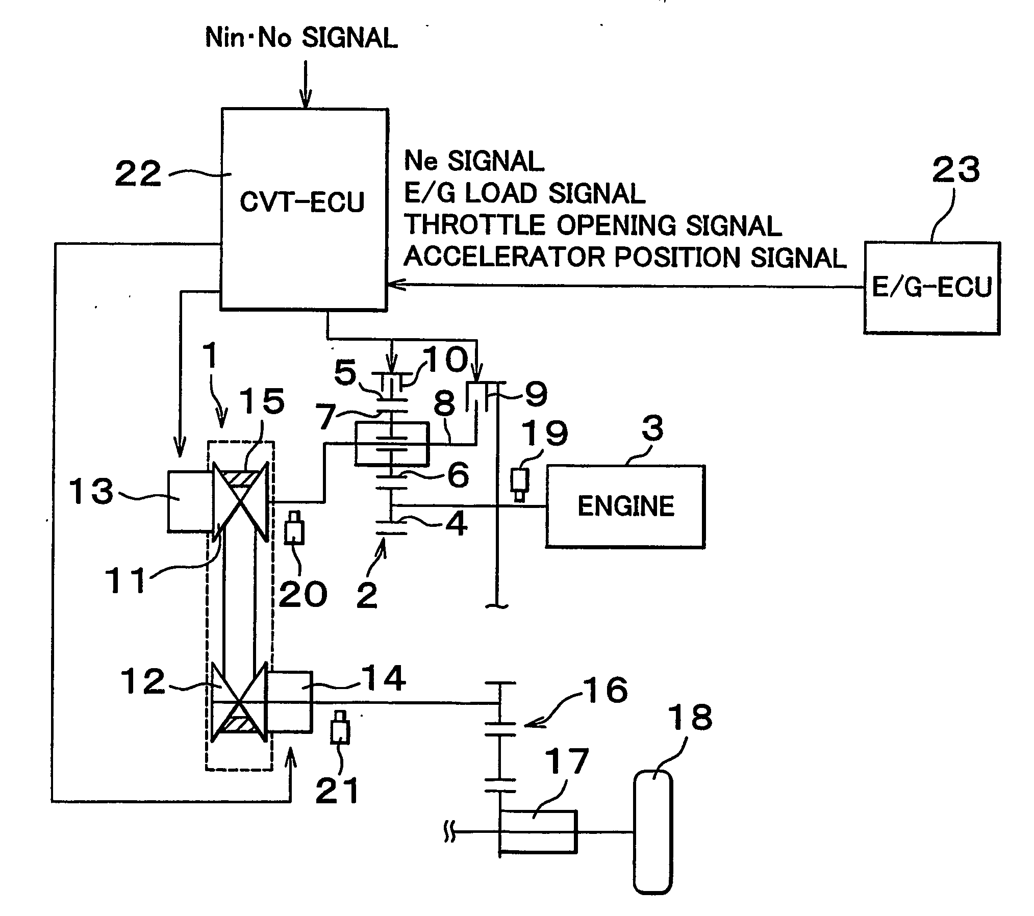
[0036] Some exemplary embodiments of the invention will be described in detail. First, a drive system and a control system of a motor vehicle to which the invention is applied will be described with reference to FIG. 14. FIG. 14 schematically shows a drive system including a belt-type continuously variable transmission (CVT) 1 as a transmission. The CVT 1 is coupled to a power source 3 via a forward / reverse-drive switching mechanism 2.

[0037] The power source 3 is a drive unit for generating power to run the vehicle, and is provided by an internal combustion engine, a combination of an internal combustion engine and an electric motor, an electric motor, or the like. In this embodiment, the power source 3 takes the form of an engine. The forward / reverse-drive switching mechanism 2 is employed since the engine 3 can rotate only in one direction, and is arranged to output the input torque as it is or in a reverse direction.

[0038] In the example shown in FIG. 14, a double-pinion type p...


PUM


Abstract

A slippage detection system for a continuously variable transmission capable of continuously changing a ratio between a speed of rotation of an input member and a speed of rotation of an output member is provided. The slippage detection system calculates a correlation coefficient relating to the input rotation speed and the output rotation speed, based on a plurality of measurement values of the input rotation speed and a plurality of measurement values of the output rotation speed, and determines slippage of the torque transmitting member in the continuously variable transmission based on the calculated correlation coefficient.

Description

BACKGROUND OF THE INVENTION [0001] 1. Field of Invention [0002] The invention relates to a slippage detection system and method for use in a continuously variable transmission capable of continuously changing the gear ratio that is a ratio between an input rotation speed and an output rotation speed of the CVT. [0003] 2. Description of Related Art [0004] As a continuously variable transmission capable of changing the gear ratio continuously, a belt-type continuously variable transmission and a toroidal type (traction-type) continuously variable transmission are known in the art. The belt-type continuously variable transmission is adapted to transmit torque and change the gear ratio by using a belt, and the toroidal type continuously variable transmission is adapted to transmit torque and change the gear ratio by using a power roller. In the belt-type continuously variable transmission, the belt is wound around drive and driven pulleys each capable of changing a groove width, and tor...

Claims


Application Information

Patent Timeline
Patent Type & Authority Applications(United States)
IPC IPC(8): F16H55/56F16H9/00F16H61/02F16H61/12F16H61/66F16H61/662
CPCF16H61/66272F16H61/6649F16H2059/465Y10T477/755Y10T477/69367Y10T477/6939Y10T477/816Y10T477/624Y10T477/6237F16H61/12F16H61/4192
Inventor IWATSUKI, KUNIHIROHOSHIYA, KAZUMIOSHIUMI, YASUHIROYAMAGUCHI, HIROYUKINISHIZAWA, HIROYUKISUZUKI, HIDEYUKIOSAWA, MASATAKA
Owner TOYOTA JIDOSHA KK
Features
  • Generate Ideas
  • Intellectual Property
  • Life Sciences
  • Materials
  • Tech Scout
  • Unparalleled Data Quality
  • Higher Quality Content
  • 60% Fewer Hallucinations
Learn More