External ultrasonic therapy

an external ultrasonic and therapy technology, applied in the field of ultrasonic therapy, can solve the problems of tissue destruction through heating or mechanical action, and the heating of the intervening layer

Inactive Publication Date: 2006-08-17
EKOS CORP
View PDF99 Cites 63 Cited by
  • Summary
  • Abstract
  • Description
  • Claims
  • Application Information

AI Technical Summary

Problems solved by technology

Prolonged exposure to intense acoustic fields causes tissue destruction through h

Method used


Image

  • External ultrasonic therapy
  • External ultrasonic therapy
  • External ultrasonic therapy

Examples


Embodiment Construction

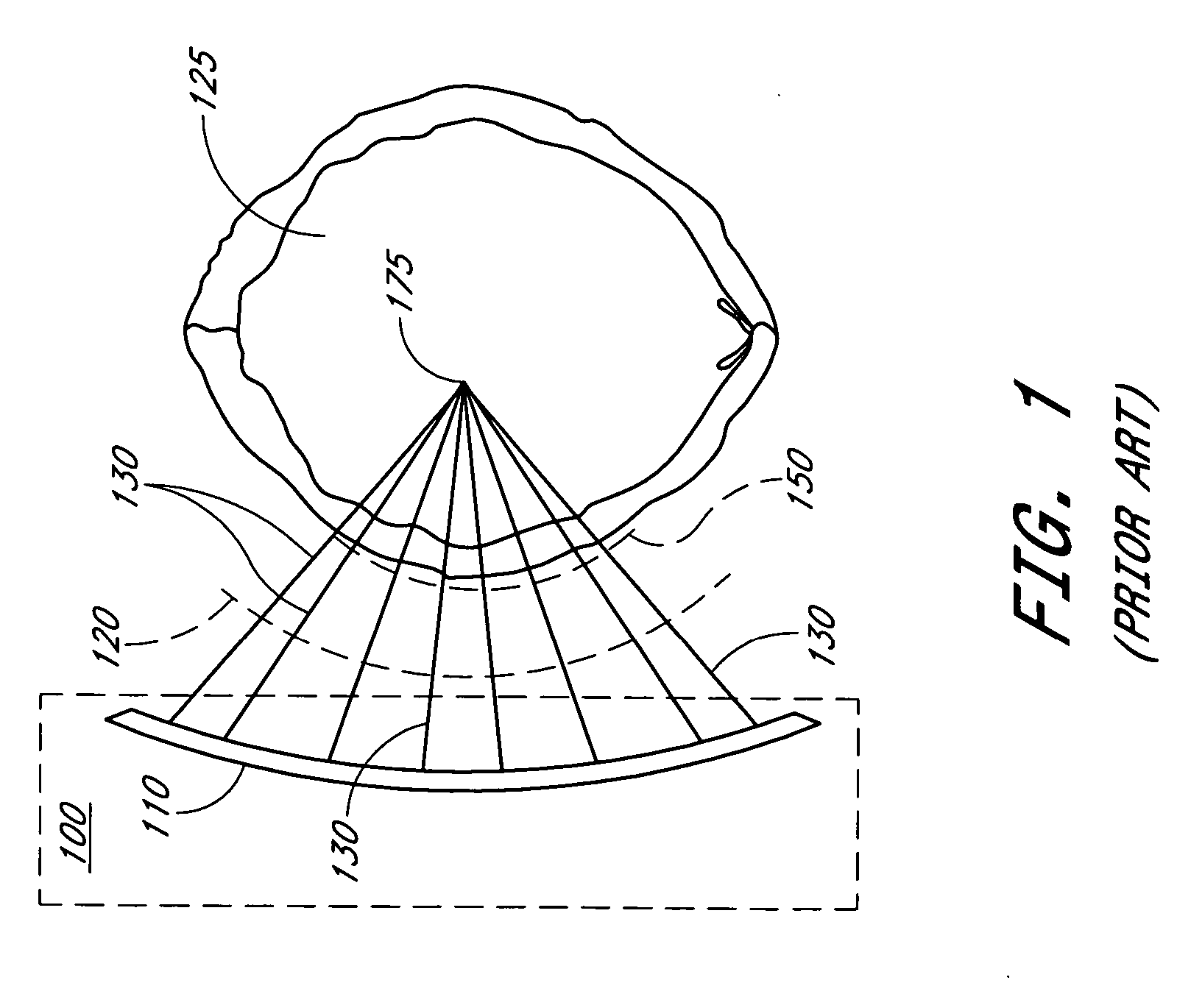
[0026] In one particular embodiment described below, an external device can deliver ultrasound, which enhances the effect of a drug configured to treat an occlusion of a blood vessel within the brain. Such an embodiment is particularly useful for treating victims of ischemic stroke. The external ultrasonic device is preferably configured to produce an acoustic field about the treatment site. For stroke treatment, the acoustic field delivered to the skull can be shaped by geometric focusing, using either physical or electronic lenses to reduce or avoid undue skull heating. FIG. 1 illustrates one embodiment of this type of external ultrasound device. As shown, the device includes an ultrasound transducer 100 that contains a lens structure 110 that produces a concave shaped wave front 120 that converges along paths 130 to a point of intended focus 175 after transiting the skull 125. The acoustic intensity at the convergence point 175 is many times higher than it acoustic intensity at t...


PUM


Abstract

A coupling pad can be used with a transducer element. Ultrasound produced by the transducer element can be propagated through the coupling pad to a patient. In one arrangement, the pad is a pouch containing a pliant substance. In other arrangements, the pad is a somewhat solid member formed of a material that transmits ultrasound waves efficiently. The pad may be configured to fit between a patient's skin and a transducer element so that output from the transducer element passes through the pad to a treatment site of the patient.

Description

RELATED APPLICATIONS [0001] This application claims the priority benefit under 35 U.S.C. § 119(e) of U.S. Provisional Application No. 60 / 627,469, filed Nov. 12, 2004, which is hereby incorporated by reference in its entirety.BACKGROUND OF THE INVENTION [0002] 1. Field of the Invention [0003] The invention relates to ultrasonic therapy, and in particular, to therapy that utilizes an external ultrasonic device configured to deliver therapeutic ultrasonic energy to a patient. [0004] 2. Description of the Related Art [0005] Ultrasonic energy may be applied to selected regions within a body to provide a therapeutic effect. In some applications, the ultrasound is generated from an extracorporeal ultrasonic transducer. Examples of such applications include ultrasonic ablation of tissue as shown in U.S. Pat. No. 4,858,613, “Localization and Therapy System for treatment of spatially oriented focal disease”, issued Aug. 22, 1989, to Fry et al.; fracture of kidney stones, as shown in U.S. Pat....

Claims


Application Information

Patent Timeline
IPC IPC(8): A61H1/00A61B8/12
CPCA61B2017/2253A61N7/00
Inventor HANSMANN, DOUGLAS R.RULE, PETER
Owner EKOS CORP
Why Eureka
Try Eureka