Metal forged product, upper or lower arm, preform of the arm, production method for the metal forged product, forging die, and metal forged product production system

Inactive Publication Date: 2006-08-24
SHOWA DENKO KK
View PDF4 Cites 15 Cited by
  • Summary
  • Abstract
  • Description
  • Claims
  • Application Information

AI Technical Summary

Benefits of technology

[0036] As described above, the method of the present invention for producing a metal forged product comprises a preliminary forging step of forming a preform by closed forging from a cylindrical material having a surface layer on a circumferential surface thereof such that the surface layer is contained in a surface region of the preform and a forging step of subjecting the preform to forging to thereby extrude the surface layer in the form of flash outside a periphery of a forged produc

Problems solved by technology

In this method, since unwanted flashes are formed on the preform, the yield of the preform on the basis of a forging material is low.
In addition, since the projection area of the preform (i.e., forged product) as viewed in the direction of pressure application is large, a large, expensive forging machine capable of applying high load is required, resulting in high production cost.
In the closed forging method disclosed by JP-A HEI 10-166842, since the surface layer is extruded through tightly sealed forging, t

Method used


Image

  • Metal forged product, upper or lower arm, preform of the arm, production method for the metal forged product, forging die, and metal forged product production system
  • Metal forged product, upper or lower arm, preform of the arm, production method for the metal forged product, forging die, and metal forged product production system
  • Metal forged product, upper or lower arm, preform of the arm, production method for the metal forged product, forging die, and metal forged product production system

Examples


example 1

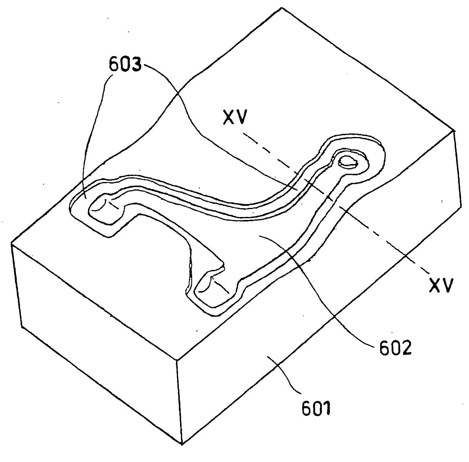
[0204] In order to produce, through the preliminary forging step, a preform of an upper arm shown in FIG. 6(a), which is a suspension part for an automobile, a cut piece of JIS 6061 aluminum alloy (i.e., forging material) having the same volume as the preform was designed as follows.

[0205] The volume of the upper arm preform was calculated by means of a CAD system programmed in a computer. On the basis of the results of the calculation, the volume of a cut piece was designed to be 862 cm3. The volume tolerance of the cut piece was determined to be ±1% on the basis of the calculated volume of the preform.

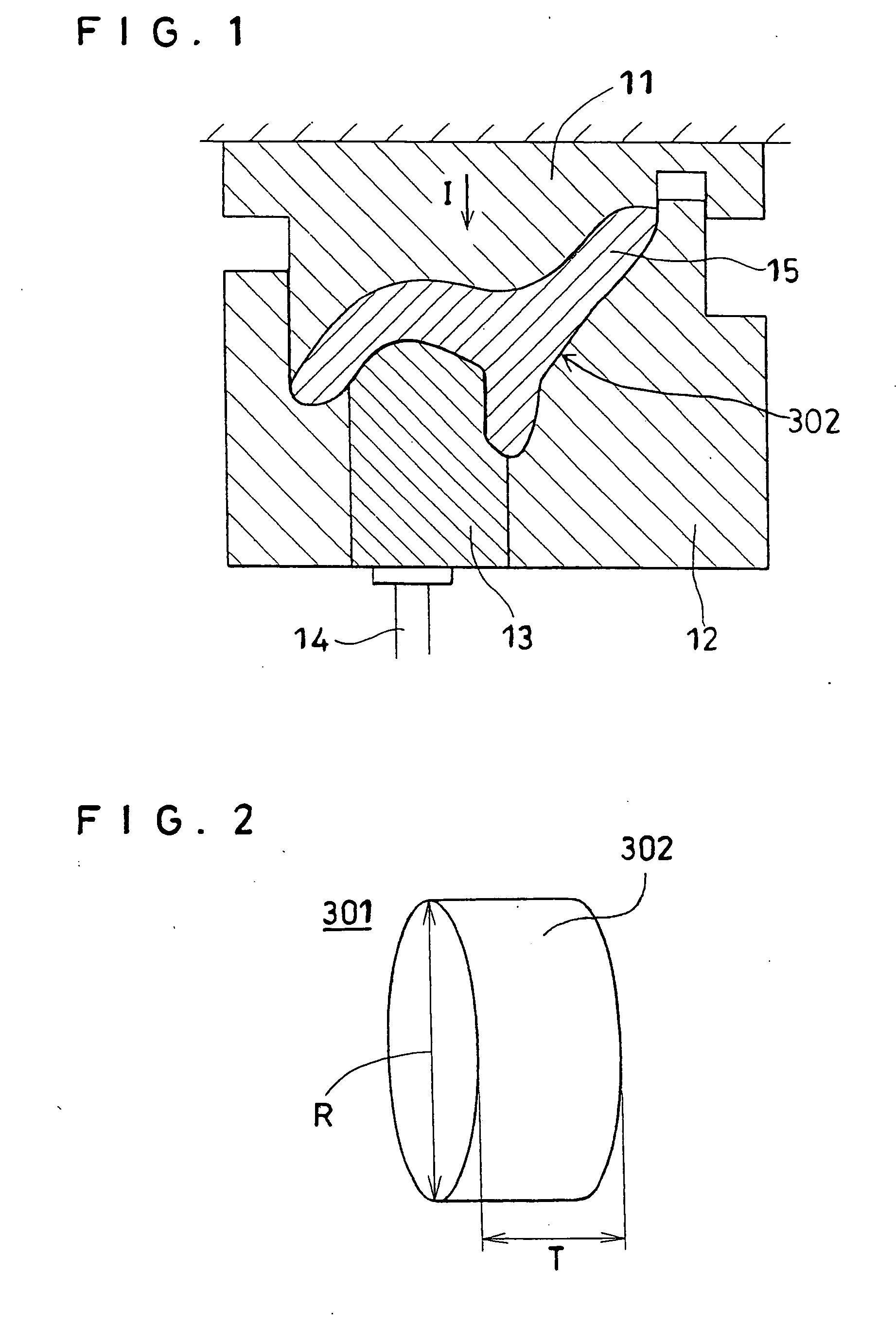
[0206] Subsequently, the thickness of the cut piece was designed to be 28 mm, which is 0.95 times the lateral length (t) represented by reference letter J (shown in FIG. 16) of a projection profile of the preform, the projection profile being formed in a direction perpendicular to the direction of pressure application I shown in FIG. 1. On the basis of the volume and thickness of t...

example 2

[0221] In order to produce an upper arm shown in FIG. 18, which is a suspension part for a vehicle, a forging preform shown in FIG. 19 of the upper arm was produced. A cut piece of JIS 6061 aluminum alloy (i.e., forging material) that had the same volume as the preform, was designed as follows.

[0222] The volume of the upper arm preform was calculated by means of a CAD system programmed in a computer. On the basis of the results of the calculation, the volume of a cut piece was designed to be 595 cm3. The volume tolerance of the cut piece was determined to be ±1% on the basis of the calculated volume of the preform.

[0223] Subsequently, the thickness of the cut piece was designed to be 30 mm, which is 0.95 times the lateral length (t) represented by reference letter N (shown in FIG. 21) of a projection profile of the preform, which profile is formed in a direction perpendicular to the direction of pressure application M shown in FIG. 20. On the basis of the volume and thickness of t...

example 3

[0232] Forging was performed under the same forging conditions as those employed in Example 1, except that the aluminum alloy species serving as a forging material was changed as described below.

[0233] In order to produce, through forging, a preform of an upper arm shown in FIG. 6(a), which is a suspension part for an automobile, there was employed, as a forging material, a cut piece of a continuously cast round bar of SU 610 aluminum alloy (Mg: 0.8 to 1.2 wt. %, Si: 0.7 to 1.0 wt. %, Cu: 0.3 to 0.6 wt. %, Cr: 0.14 to 0.3 wt. %, Mn: 0.14 to 0.3 wt. %, and Al and impurities: balance), the cut piece having the same volume as the preform.

[0234] The yield by weight of the preform on the basis of the forging material was found to be about 99%.

[0235] The surface layer of the forging material observed was distributed throughout a circumferential surface 62 of the preform, and parallel surfaces 63 of the preform were found not to have the surface layer. The cross sections of three branch...


PUM

PropertyMeasurementUnit
Thicknessaaaaaaaaaa
Thicknessaaaaaaaaaa
Flow rateaaaaaaaaaa

Abstract

A method for producing a metal forged product having a plurality of branches includes a preliminary forging step of forming a preform by closed forging from a cylindrical material (301) having a surface layer (302) on a circumferential surface thereof such that the surface layer is contained in a surface region of the preform; an intermediate forging step of subjecting the preform to forging to thereby extrude the surface layer in the form of flash outside a periphery of a forged product corresponding to a target product; a final forging step of forging the forged product into a product assuming a target product shape; and a flash removal step of removing the flash containing the surface layer from the product assuming a target product shape to thereby produce a target forged product. The forged product is enhanced in mechanical characteristics and has no flash removal mark. Since the cylindrical material having a surface layer on a circumferential surface thereof is used, the power required for the steps can be reduced to enhance the yield of the products on the basis of the forging material.

Description

CROSS REFERENCE TO RELATED APPLICATIONS [0001] This application is an application filed under 35 U.S.C. §111(a) claiming the benefit pursuant to 35 U.S.C. §119(e)(1) of the filing date of Provisional Application Ser. No. 60 / 448,531 filed Feb. 21, 2003 pursuant to 35 U.S.C. §111(b).TECHNICAL FIELD [0002] The present invention relates to a metal forged product, an upper or lower arm, a preform of the arm, a method for producing the product, a forging die, and a metal forged product production system. BACKGROUND ART [0003] Recently, in place of iron material, aluminum alloy has been increasingly employed for producing suspension parts for vehicles in order to reduce the weight of the parts. Particularly, the suspension parts for vehicles have been produced through forging in order to enhance their mechanical strength and to reduce the amount of raw material employed for producing a product. Examples of the parts employed in a vehicle suspension include an upper arm and a lower arm. [00...

Claims


Application Information

Patent Timeline
IPC IPC(8): B21J5/02B21K1/12B21K1/74B21K1/76B21K3/00
CPCB21J5/02B21K1/12B21K1/74B21K1/76B21K1/762B21K3/00
Inventor NAKAHARA, TAKAFUMIAKIYAMA, MITSUHARU
Owner SHOWA DENKO KK
Why Eureka
Try Eureka