Flexible solar cell and method of producing the same

Inactive Publication Date: 2006-08-24
SAMSUNG ELECTRONICS CO LTD
View PDF1 Cites 101 Cited by
  • Summary
  • Abstract
  • Description
  • Claims
  • Application Information

AI Technical Summary

Benefits of technology

[0012] The present disclosure provides a cylindrical flexible solar cell whi

Problems solved by technology

However, silicone solar cells have very high production costs, which make it difficult to practicalize the cells, and there are difficulties in improving the cell efficiency of silicone solar cells.
However, since it is impossible to bend a solar cell produced with a glass substrate, the substrate is rarely used in applications where flexible solar cells are needed.
However, these solar cells exhibit low photovoltaic conversion efficiencies c

Method used


Image

  • Flexible solar cell and method of producing the same
  • Flexible solar cell and method of producing the same
  • Flexible solar cell and method of producing the same

Examples


example 1

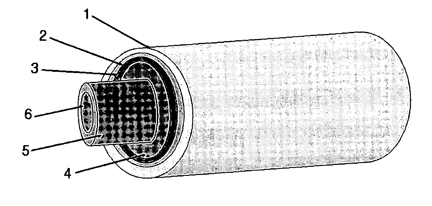
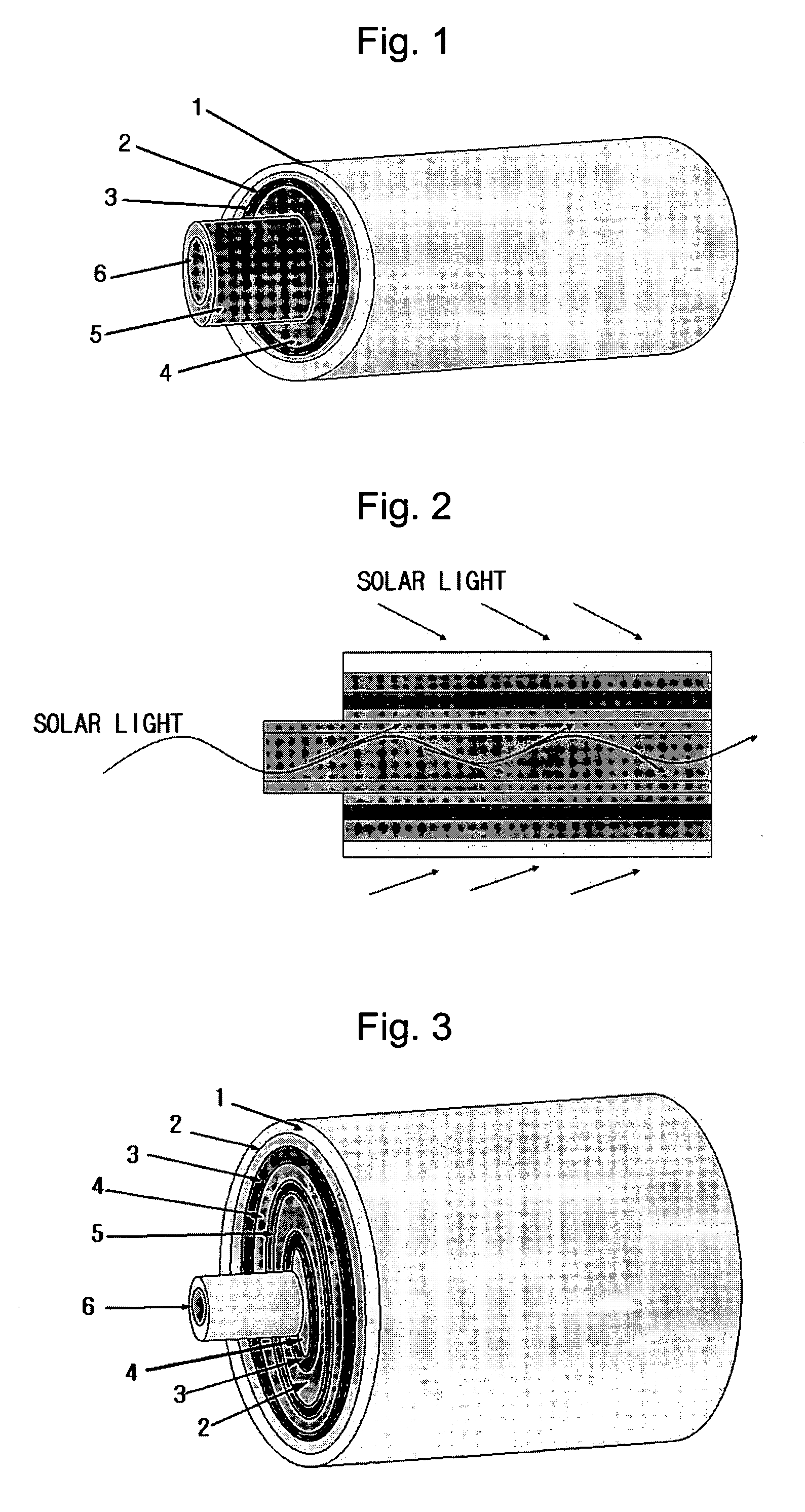
[0071] A cylindrical counter electrode was formed by sequentially coating PET and ITO on an optical fiber having a length of 5 cm and a diameter of 1 mm. A gel-like electrolyte solution of I3− / I−, produced by dissolving 0.8 M of 1,2-dimethyl-3-octyl-imidazolium iodide and 40 mM of I2 in N-methyl-2-pyrrolidone, was coated on the cylindrical surface of the counter electrode.

[0072] Separately, a titanium dioxide colloidal solution was prepared by adding titanium isopropoxide and acetic acid to an autoclave maintained at 220° C. and carrying out hydrothermal synthesis. The obtained solution was subjected to solvent evaporation until the proportion of titanium dioxide became 12% by weight, to prepare a titanium dioxide colloidal solution containing nano-sized particles (the particle size being in the range of about 5 to 30 nm).

[0073] The cylindrical surface having the electrolyte layer formed thereon was coated with the titanium dioxide colloidal solution, and then the cell assembly wa...

example 2

[0075] First, slurries for a heavy mineral oil, a counter electrode, an electrolyte layer, a metal oxide layer, a dye and a conductive transparent substrate, respectively, were prepared.

[0076] PET and ITO were used for the counter electrode and the conductive transparent substrate, respectively, and an electrolyte solution of I3− / I− formed by dissolving 0.8 M 1,2-dimethyl-3-octyl-imidazolium and 40 mM I2 in N-methyl-2-pyrrolidone was used for the electrolyte layer. A 0.2 mM solution of ruthenium dithiocyanate 2,2′-bipyridyl-4,4′-dicarboxylate was used as the dye.

[0077] For the metal oxide layer, a titanium dioxide colloidal solution was prepared by adding titanium isopropoxide and acetic acid to an autoclave maintained at 220° C. and carrying out hydrothermal synthesis. The obtained solution was subjected to solvent evaporation until the proportion of titanium dioxide became 12% by weight, to prepare a titanium dioxide colloidal solution containing nano-sized particles (the partic...

example 3

[0079] A cylindrical conductive transparent electrode was formed by sequentially coating PET and ITO on the surface of an optical fiber having a length of 5 cm and a diameter of 1 mm. A gel-like electrolyte solution of I3− / I−, produced by dissolving 0.8 M of 1,2-dimethyl-3-octyl-imidazolium iodide and 40 mM of I2 in N-methyl-2-pyrrolidone was coated on the cylindrical surface of the conductive transparent electrode.

[0080] Separately, a titanium dioxide colloidal solution was prepared by adding titanium isopropoxide and acetic acid to an autoclave maintained at 220° C. and carrying out hydrothermal synthesis. The obtained solution was subjected to solvent evaporation until the proportion of titanium dioxide became 12% by weight, to prepare a titanium dioxide colloidal solution containing nano-sized particles (the particle size being in the range of about 5 to 30 nm).

[0081] The cylindrical surface having the electrolyte layer formed thereon was coated with the titanium dioxide collo...


PUM


Abstract

Provided are a cylindrical flexible solar cell which is made of only flexible materials so that the cell can freely bend, has a cylindrical shape which allows the cell to absorb solar light at any angle of illumination, and has a large surface area and high efficiency; and a method of producing the same.

Description

CROSS-REFERENCE TO RELATED PATENT APPLICATION [0001] Prioirty is claimed to Korean Patent Application No. 10-2005-0010990, filed on Feb. 5, 2005, in the Korean Intellectual Property Office, the disclosure of which is incorporated herein in its entirety by reference. BACKGROUND OF THE DISCLOSURE [0002] 1. Field of the Disclosure [0003] The present disclosure relates to a cylindrical flexible solar cell and a method of producing the same, and more particularly, to a cylindrical flexible solar cell which is made of only flexible materials so that the cell can freely bend, has a cylindrical shape which allows the cell to absorb solar light at any angle of illumination, and has a large surface area and high efficiency, and a method of producing the same. [0004] 2. Description of the Related Art [0005] In an attempt to address recent energy-related problems, research has been carried out to find replacements for existing fossil fuels. In particular, extensive research has been carried out...

Claims


Application Information

Patent Timeline
IPC IPC(8): H01L31/042
CPCH01G9/2031H01G9/2068H01G9/2086H01L51/0086Y02E10/542H10K85/344G09B5/06G09B1/40G06K7/10009G06K19/07758F21K9/00
Inventor NAM, JUNG-GYUPARK, SANG-CHEOLJUNG, WON-CHEOLPARK, YOUNG-JUN
Owner SAMSUNG ELECTRONICS CO LTD
Why Eureka
Try Eureka