Breaker for providing successive trip mechanism based on PTC current-limiting device
Active Publication Date: 2006-08-24
LS IND SYETEMS CO LTD
View PDF7 Cites 7 Cited by
Summary
Abstract
Description
Claims
Application Information
AI Technical Summary
This helps you quickly interpret patents by identifying the three key elements:
Problems solved by technology
Method used
Benefits of technology
Benefits of technology
[0027] The present invention is designed to solve the problems of the prior art, and therefore it is an object of the present invention to provide a breaker for providing successive trip mechanism, which is capable of preventing deterioration of a PTC current-limiting device, preventing a previously released switch from being closed again, and easily switching a fault current toward the PTC current-limiting device.
Problems solved by technology
The arc operated toward the extinction grid results in a voltage drop of the line, which limits a fault current flowing on the line, and the limited fault current is completely broken at an artificial current zero point by means of cooling and division of the arc.
However, U.S. Pat. No. 2,639,357 has a drawback that a fault current is not suitably switched to the current-limiting device.
However, U.S. Pat. No. 4,878,038 has a problem that the current-limiting device connected with a line in series is continuously heated due to Joule heat at ordinary times, so a power loss is caused even when an ordinary load current flows.
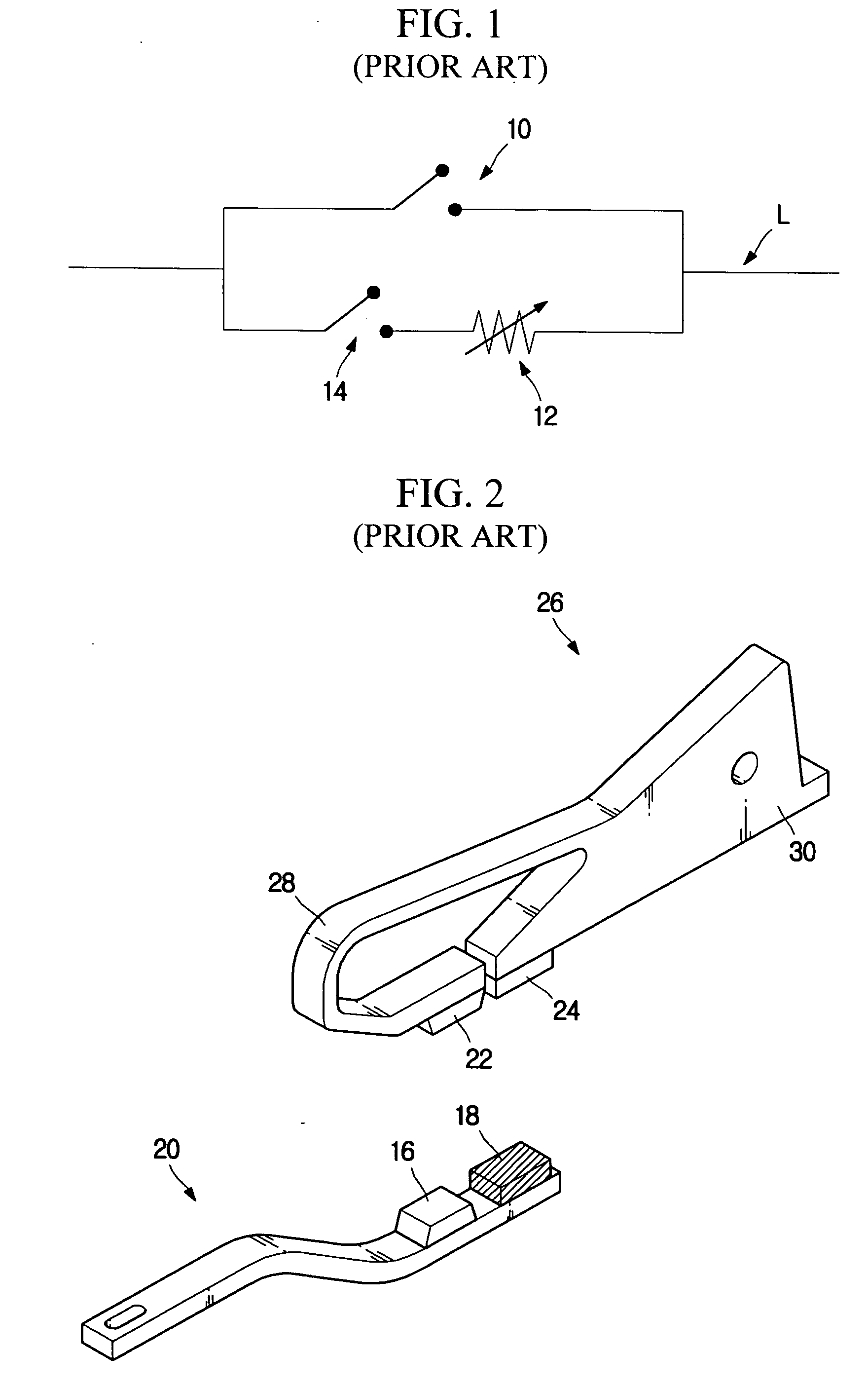
Thus, a problem of power loss caused by Joule heat generated in the current-limiting device 12 does not happen.
Thus, the arc generated during the breaker closing procedure is apt to melt, damage or divide the second fixed contact point 24 composed of a PTC current-limiting device.
Third, the second fixed contact point 24 is composed of a PTC current-limiting device that is weaker than general contact point materials, so it is apt to be easily deformed or damaged.
In addition, if the contact point itself is composed of a PTC current-limiting device, there is a drawback of shortening an electric life of the breaker as well as a mechanical life.
However, since the second fixed contact point 18 is composed of a PTC current-limiting device, it is impossible to use brazing for attachment of the contact points.
Method used
Image
Click on the blue label to locate the original text in one second.
Reading with bidirectional positioning of images and text.
Examples
first embodiment
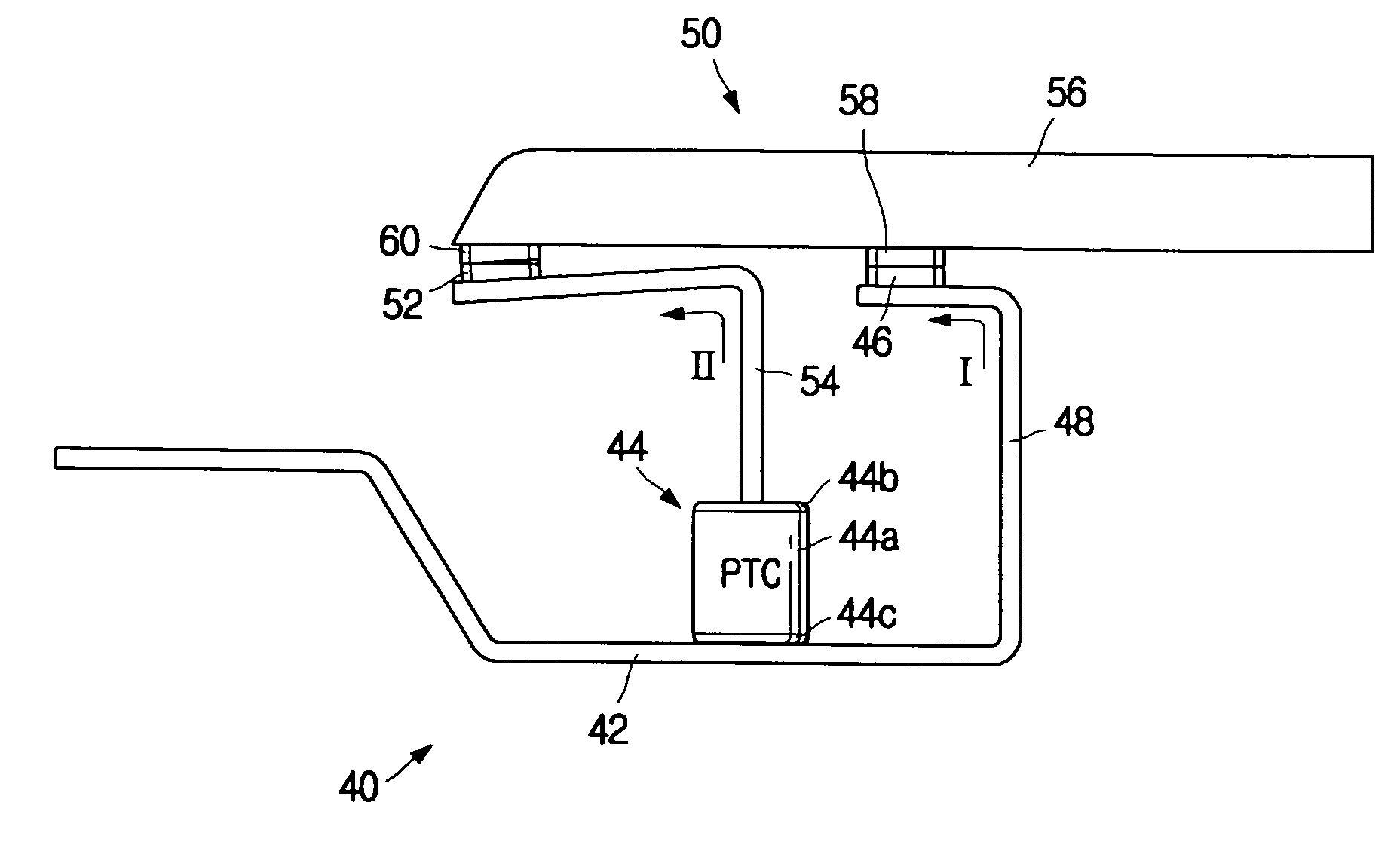
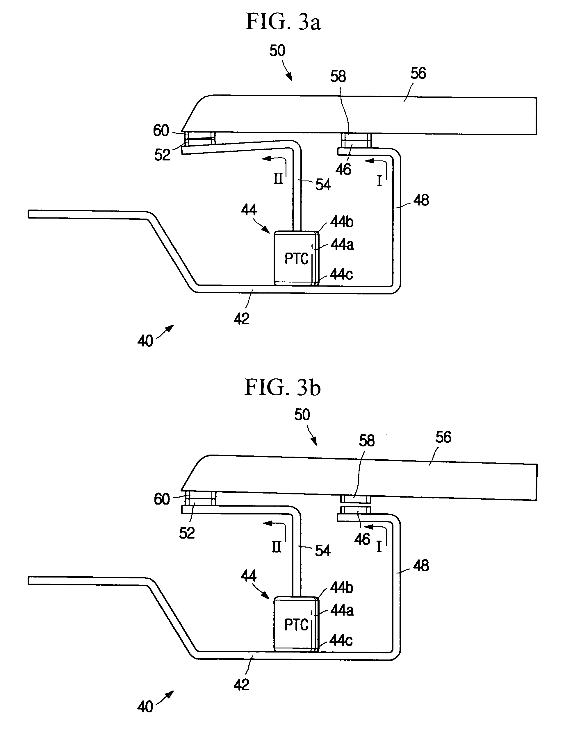
[0051]FIGS. 3a to 3c respectively show a breaker-closed state, a first switch tripped state, and a first / second switch tripped state of a breaker according to the present invention.
[0052] The breaker according to the first embodiment of the present invention includes a fixed arm 40 and a movable arm 50 in brief as shown in FIGS. 3a to 3c. The fixed arm 40 includes a fixed arm member 42 having one end electrically connected to a power source of a line, a PTC (Positive Temperature Coefficient) current-limiting device 44 attached to the fixed arm member 42, a first fixed contact point 46, a first fixed arm conductor 48 to which the first fixed contact point 46 is attached and guiding electric flow toward the first fixed contact point 46, a second fixed contact point 52, and a second fixed arm conductor 54 to which the second fixed contact point 52 is attached and guiding electric flow toward the second fixed contact point 52.
[0053] The second fixed arm conductor 54 has a geometric str...
second embodiment
[0072]FIGS. 4a to 4c respectively show a breaker-closed state, a first switch tripped state, and a first / second switch tripped state of a breaker according to the present invention.
[0073] According to the second embodiment of the present invention, as shown in FIGS. 4a to 4c, a second vertical fixed arm conductor 54a and a second horizontal fixed arm conductor 54b are coupled to be pivotable on the center of a rotary axis 62, and the second vertical and horizontal fixed arm conductors 54a and 54b are elastically coupled using a torsion spring 64. Other configurations of the second embodiment are substantially identical to those of the first embodiment.
[0074] Like the first embodiment, an angle θ1 between the first fixed and movable contact points 46 and 58 is relatively greater than an angle θ2 between the second fixed and movable contact point 52 and 60 in the breaker of the second embodiment, as shown in FIG. 4c. Thus, if the breaker is closed as shown in FIG. 4a, the second hori...
third embodiment
[0076]FIGS. 5a to 5c respectively show a breaker-closed state, a first switch tripped state, and a first / second switch tripped state of a breaker according to the present invention.
[0077] According to the third embodiment of the present invention, a guide housing 70 having a compression spring 66 mounted therein and an opening 68 formed at its lower end is provided below the movable arm 50 as shown in FIGS. 5a to 5c. In addition, the second movable contact point 60 is received in the guide housing 70 so that its one side faces the compression spring 66 and the other side is exposed outward to face the second fixed contact point 52. In addition, the second fixed contact point 52 has a shape corresponding to the opening 68 so that it may be inserted through the opening 68 prepared in the lower portion of the guide housing 70. Other configurations of the third embodiment are substantially identical to those of the first embodiment.
[0078] Like the first embodiment, an angle θ1 between ...
PUM
Abstract
Disclosed is a breaker for providing successive trip mechanism based on PTC current-limiting device, which includes a first switch having first fixed / movable contact points; a second switch having second fixed / movable contact and connected to the first switch in parallel; PTC current-limiting device connected to the first and second switches in parallel or series and allowing a change of current flow direction from the first switch to the second switch at a fault current; a movable arm to which the movable contact points are installed at an interval therebetween and opening / closing the switches by operating the movable contact points; a fixed arm including first and second fixed arm conductors for guiding current flow toward the first fixed contact point in a normal loadcurrent mode and guiding current flow toward the second fixed contact point via the PTC current-limiting device in a fault current mode; and a successive trip means for elastically biasing the second switch by operation of the movable arm in a closing direction when both switches are closed and successively tripping both switches using time taken for releasing the elastic bias of the second switch when the movable arm is operated in a tripping direction.
Description
BACKGROUND OF THE INVENTION [0001] 1. Field of the Invention [0002] The present invention relates to a breaker employing a current-limiting device having PTC (Positive Temperature Coefficient) characteristics, and more particularly to a breaker for limiting and breaking a fault current using successive trips by electrically connecting a current-limiting device having PTC characteristics to a plurality of switches. [0003] 2. Description of the Related Art [0004] Breakers are widely used for protecting lines and power equipments installed on the lines against a fault current such as a short circuit current in a power system such as a transmission system and a distribution system. [0005] A conventional breaker includes a switch having a fixed contact point and a movable contact point and serially connected to a line for selective opening and closing, an extinction grid for extinguishing an arc generated in the switch while a fault current of the line is broken, and a movable contact po...
Claims
Application Information
Patent Timeline
Application Date:The date an application was filed.
Publication Date:The date a patent or application was officially published.
First Publication Date:The earliest publication date of a patent with the same application number.
Issue Date:Publication date of the patent grant document.
PCT Entry Date:The Entry date of PCT National Phase.
Estimated Expiry Date:The statutory expiry date of a patent right according to the Patent Law, and it is the longest term of protection that the patent right can achieve without the termination of the patent right due to other reasons(Term extension factor has been taken into account ).
Invalid Date:Actual expiry date is based on effective date or publication date of legal transaction data of invalid patent.

