
Radiological imaging apparatus and positron emission tomographic apparatus

Inactive Publication Date: 2006-08-24
HITACHI LTD
View PDF16 Cites 23 Cited by
  • Summary
  • Abstract
  • Description
  • Claims
  • Application Information

AI Technical Summary

Benefits of technology

[0007] The partition member prevents noise generated by the voltage adjustment device from reaching the first region, so that the γ-ray detection signal outputted from the semiconductor radiation detector can avert any effect from noise. Hence, the utilizable energy region of the γ-ray detection signal is expanded, and the γ-ray detection signal of low energy can be also used. That is, the γ-ray detection signal generated owing to γ-rays scattered by the semiconductor radiation detector can be used for creating tomographic information. This increases a detection sensitivity of the radiological imaging apparatus, and the examination time for the examinee is shortened.
[0008] Even in case the voltage adjustment device is provided outside of the storage member without providing the partitioning member in the storage member, the same effect as described above can be obtained.
[0009] According to the present invention, the γ-ray detection signal generated owing to the γ-rays scattered by the semiconductor radiation detector can be used for creating tomographic information. Hence, the detection sensitivity is increased, and the examination time can be shortened.

Problems solved by technology

When such a γ-ray radiation detection signal of low energy, for example, a γ-ray detection signal of 211 keV is affected by noise, its γ-ray detection signal cannot be used.

Method used


Image

  • Radiological imaging apparatus and positron emission tomographic apparatus
  • Radiological imaging apparatus and positron emission tomographic apparatus
  • Radiological imaging apparatus and positron emission tomographic apparatus

Examples


Embodiment Construction

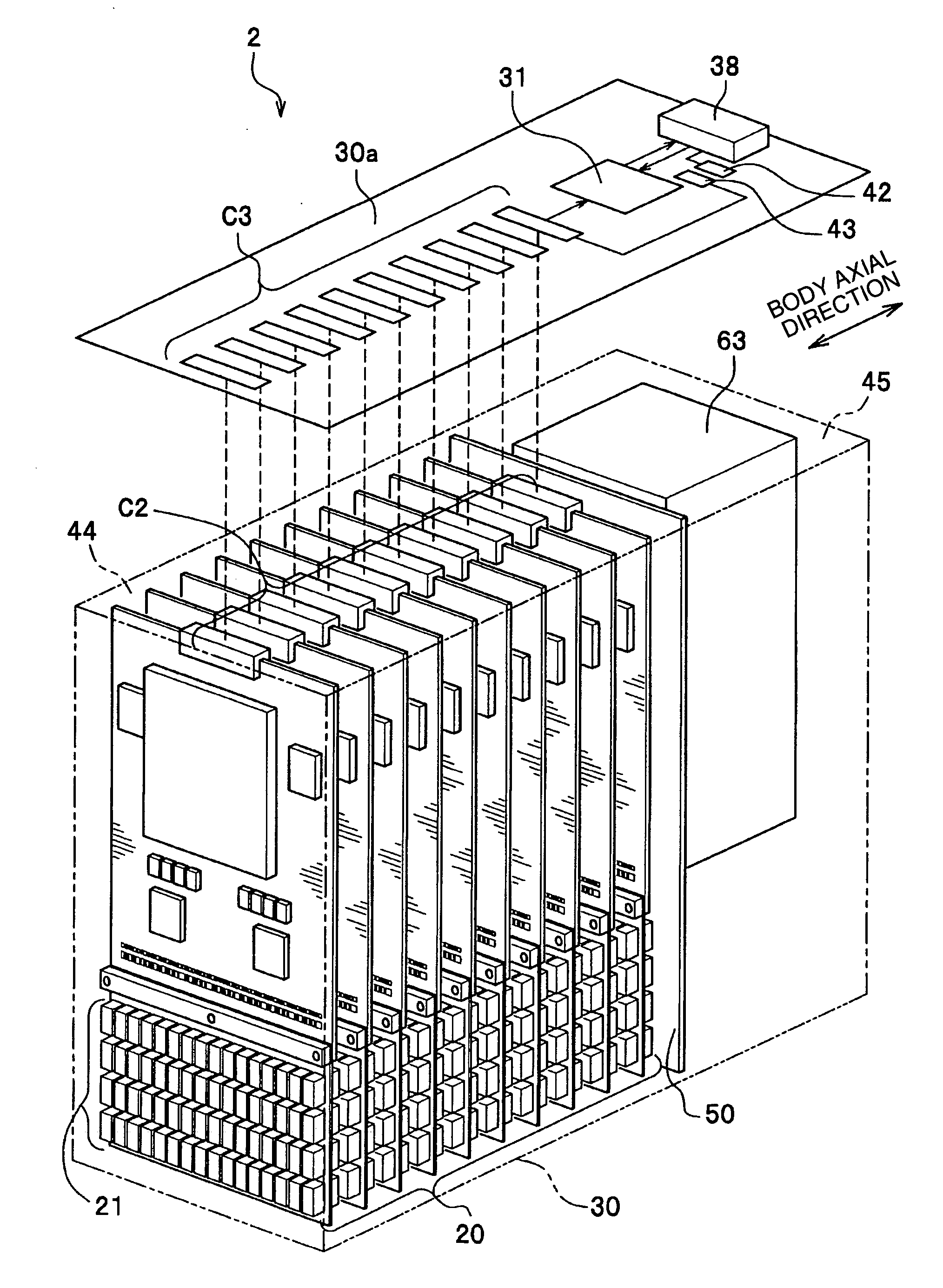
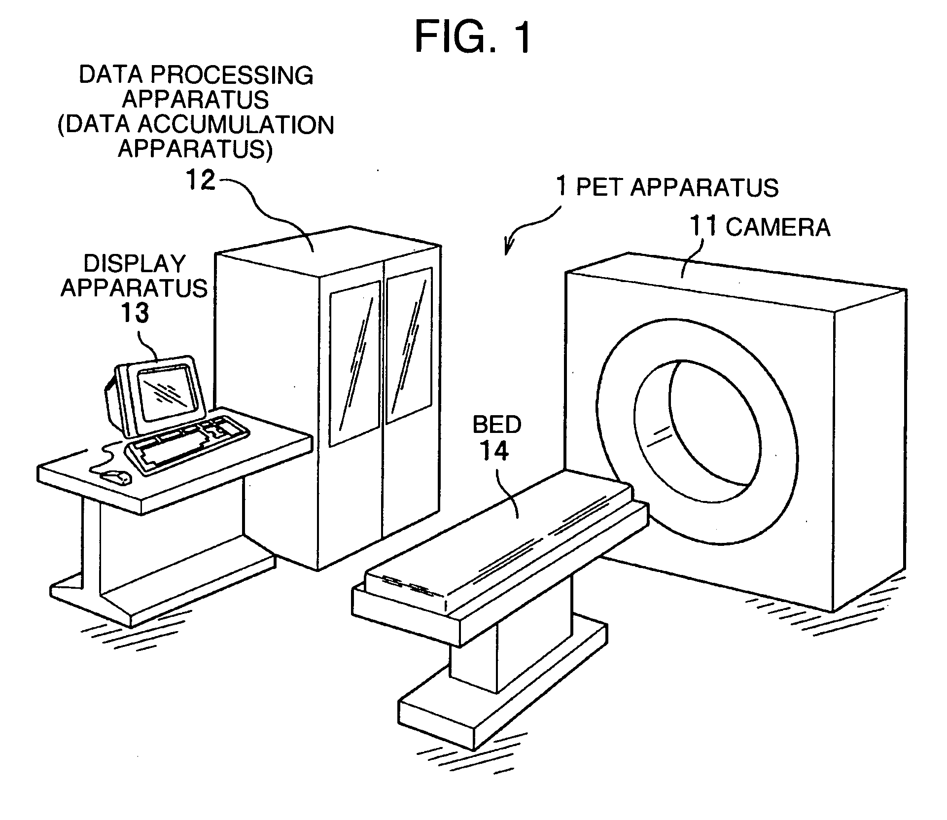
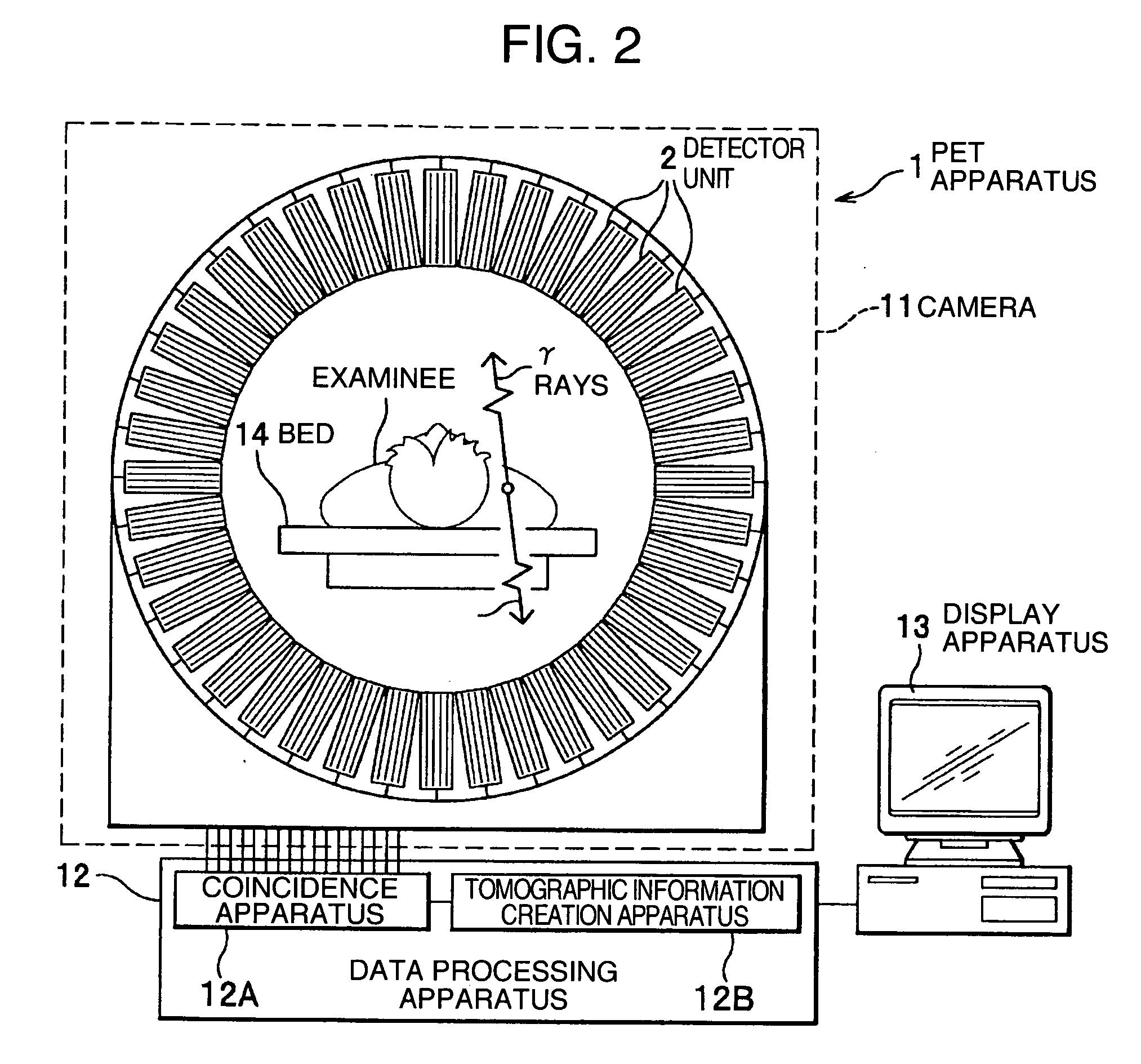
[0020] A radiological imaging apparatus and a voltage adjustment device which are one preferable embodiment of the present invention will be described below in detail with reference to the drawings from time to time. Hereinafter, a description will be made on the radiological imaging apparatus of the present embodiment, disposition (layout) of each element such as an analogue ASIC and the like on a substrate, and elements and the like applied to the present embodiment such as unitization of the substrate and the like. The analogue ASIC means an ASIC (Application Specific Integrated Circuit) processing an analogue signal, which is an IC for specific application, and is a sort of LSI.

>

[0021] A positron emission tomographic apparatus (hereinafter referred to as [PET (Positron Emission Tomography) apparatus]) 1 which is a radiological imaging apparatus of the present embodiment will be described by using FIG. 1. The PET apparatus 1 is constituted by including a camera (image pickup app...


PUM


Abstract

A positron emission tomography apparatus installs a plurality of detector units in the circumference of a bed. The detector unit installs a plurality of combined substrates including detectors, analogue ASICs, and a digital ASIC and a voltage adjustment device inside a housing. A partition plate installed inside the housing separates the region inside the housing into a first region installed with the combined substrates and a second region installed with the voltage adjustment device. The partition plate blocks noise generated in the voltage adjustment device so as not to affect γ-ray detection signals outputted from the detectors, thereby preventing the effect of the noise generated in the voltage adjustment device toward γ-ray detection signals and shortening the examination time.

Description

BACKGROUND OF THE INVENTION [0001] The present invention relates to a radiological imaging apparatus and a positron emission tomographic apparatus. [0002] In the conventional radiological imaging apparatus, there has been an apparatus in which γ-rays emitted from an examinee who is a subject to be examined is detected by using a detector comprising a scintillator, a photomultiplier tube, and the like so that a tomographic of the subject is obtained (for example, JP-U-7-29489 (paragraphs [0007]-[0008], FIG. 1, FIG. 2)). This detector, for example, is constituted such that a large photomultiplier tube (referred to also as photomul) is placed behind a single crystal such as a sheet of big NaI and the like, and is formed in a single layer in the direction of the radiation of γ-rays, and 511 KeV or around that value which is an energy of γ-rays from the subject is detected. Consequently, no energy of low γ-rays is detected. Further, there has been disclosed a technology for solving a hea...

Claims


Application Information

Patent Timeline
IPC IPC(8): G01T1/166
CPCG01T1/2985
Inventor UENO, YUUICHIROUAMEMIYA, KENSUKEYANAGITA, NORIHITOISHITSU, TAKAFUMISEINO, TOMOYUKIMATSUMOTO, TAKASHIIRIKURA, SHINOBU
Owner HITACHI LTD
Learn More