Fuel cell system and method of controlling same

a fuel cell and system technology, applied in the direction of battery/fuel cell control arrangement, cell components, electric devices, etc., can solve the problems of insufficient diffusion of reactant gases, drop in cell voltage, and low cell voltage, so as to ensure the power generation performance of a fuel cell, reduce the number of parts, cost and power consumption

Inactive Publication Date: 2006-08-24
HONDA MOTOR CO LTD
View PDF0 Cites 3 Cited by
  • Summary
  • Abstract
  • Description
  • Claims
  • Application Information

AI Technical Summary

Benefits of technology

[0012] It is thus the object of the present invention to provide a fuel cell system that can suitably grasp the power generating state of a cell and ensure the power generation performance of a fuel cell while minimizing the number of parts, cost and power consumption, and a method of controlling the same.

Problems solved by technology

This leads to insufficient diffusion of the reactant gases, which may lower the cell voltage.
Also, when an MEA is excessively dry, generation of electrical power does not fully take place, leading to a drop in cell voltage.
When the voltage of a cell drops, the conductivity of protons (hydrogen ions) produced at the anode side of the solid polymer electrolyte membrane of the MEA falls, leading to excessive heat generation due to movement of the protons from the anode side to the cathode side.
As a result, the temperature of the fuel cell rises, causing degradation of the components (electrolyte membrane, catalyst layer, separators) constituting the fuel cell.
In this state, the performance of the failed cell suffers due to the heat generation that occurs at the failed cell due to the application of the electromotive force of the other cells, in addition to heat generation by-power generation.
The problem therefore arises that when performing control using a sensor with a wide range of detection, the detection accuracy within the cell voltage range during normal operation falls.
Also, installing another sensor just to detect drops in the cell voltage, apart from the sensor that detects the cell voltage during normal operation, complicates the entire system, leading to an increase in the number of components and cost as well as power consumption.

Method used


Image

  • Fuel cell system and method of controlling same
  • Fuel cell system and method of controlling same
  • Fuel cell system and method of controlling same

Examples


Embodiment Construction

[0029] The fuel cell system in the embodiment of the present invention and method of controlling the same is described below with reference to the accompanying drawings. The present embodiment describes a fuel cell system in which a fuel cell is mounted in a vehicle.

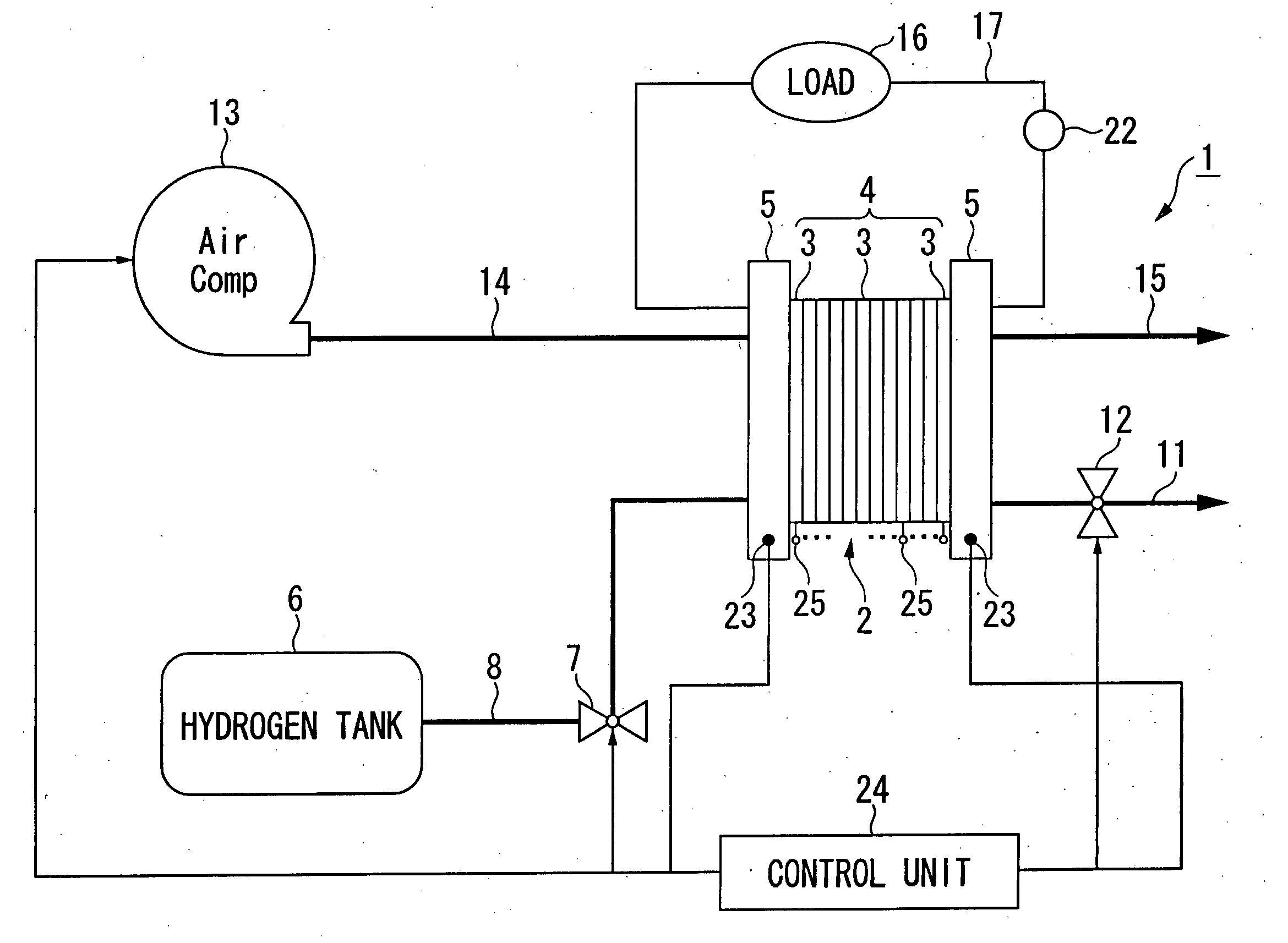
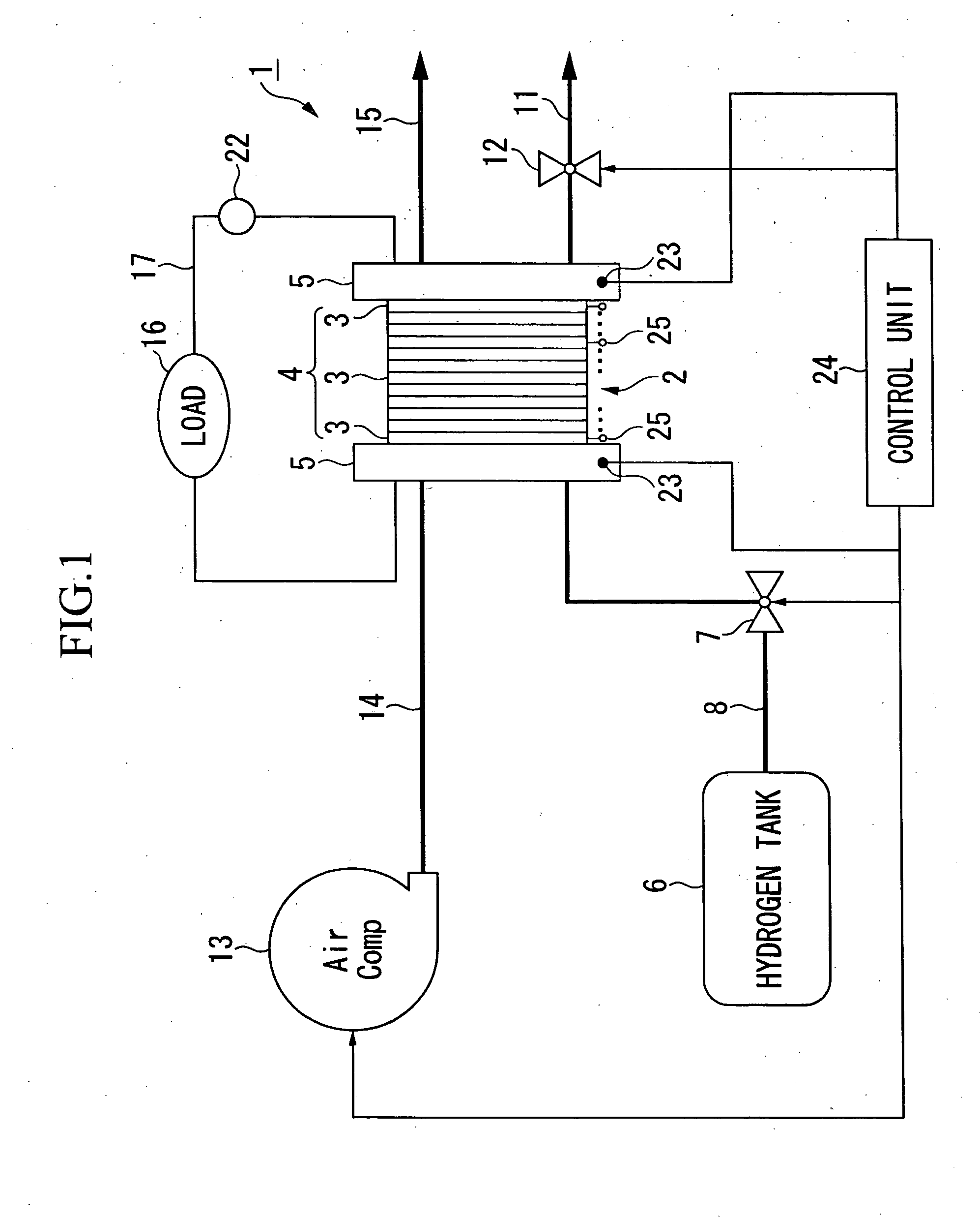
[0030]FIG. 1 is an overall configuration diagram of the fuel cell system in the embodiment of the present invention. A fuel cell 2 shown in the drawing consists of a stack 4 composed of a plurality of cells 3 stacked together, with the stack 4 being sandwiched by terminal plates 5. Each cell 3 has a membrane and electrode assembly (MEA), in which a solid polymer electrolyte membrane made of, for example, a solid polymer ion-exchange membrane is held between an anode and a cathode, with this membrane and electrode assembly being sandwiched by separators. Hydrogen is supplied to the anode of each cell as fuel, while air including oxygen is supplied to the cathode as oxidant. Hydrogen ions produced at the cathode by cataly...


PUM

PropertyMeasurementUnit
voltageaaaaaaaaaa
voltagesaaaaaaaaaa
temperatureaaaaaaaaaa

Abstract

A fuel cell system includes a fuel cell having a stack composed of stacked cells that generate electrical power from anode gas and cathode gas; a cell voltage measuring device connected to the cells to measure the voltages of the cells, the cell voltage measuring device outputting a first predetermined value as a measurement value when the voltage of the cell being measured is at or below a detection limit; a stack voltage measuring device connected to the stack that measures the voltage of the stack; and a control unit that restricts the current flowing though the fuel cell when the difference between the sum of the individual voltages of the cells measured by the cell voltage measuring device and the voltage of the stack measured by the stack voltage measuring device exceeds a second predetermined value.

Description

BACKGROUND OF THE INVENTION [0001] 1. Field of the Invention [0002] The present invention relates to a fuel cell system provided with a fuel cell of a structure having a stack including a plurality of stacked cells, and a method of controlling same. [0003] Priority is claimed on Japanese Patent Application No. 2005-42071, filed Feb. 18, 2005, the content of which is incorporated herein by reference. [0004] 2. Description of Related Art [0005] In recent years, a fuel cell vehicle equipped with a fuel cell as a vehicle drive source has been proposed. As this type of fuel cell, there is known one having a stack including a plurality of cells, each cell consisting of a membrane and electrode assembly (MEA), in which a solid polymer electrolyte membrane is held between an anode and a cathode, and sandwiched by separators. By introducing hydrogen (fuel gas) to the anode and air (oxidizing gas) to the cathode, electricity is generated by an electrochemical reaction between the hydrogen and...

Claims


Application Information

Patent Timeline
Patent Type & Authority Applications(United States)
IPC IPC(8): H01M8/04B60L11/18
CPCB60L3/0046B60L3/0053B60L11/1881B60L11/1892B60L11/1894H01M8/04552H01M8/04559H01M8/04671H01M8/04731H01M8/0491H01M8/04955H01M2008/1095H01M2250/20Y02T90/34Y02E60/50Y02T90/32B60L58/30B60L58/33B60L58/34Y02T90/40
Inventor FUJII, YOSUKETAKAI, TAKAHIRO
Owner HONDA MOTOR CO LTD
Why Eureka
Try Eureka