Rail stent and methods of use

a technology of stents and rails, applied in the field of rail stents and methods of use, can solve the problems of limiting the size, type and location of the vessels within which a stent may be placed, affecting the use of bifurcated, branched or connected stents, and causing aneurysms to eventually ruptur

Inactive Publication Date: 2006-08-24
TSUNAMI INNOVATIONS
View PDF4 Cites 267 Cited by
  • Summary
  • Abstract
  • Description
  • Claims
  • Application Information

AI Technical Summary

Benefits of technology

[0029] In some embodiments, the at least one constraining element comprises an expandable layer and actuating comprises causing the expandable layer to relax. Causing the expandable layer to relax may comprise heating the expandable layer. Relaxation of the expandable layer allows the stent to transition toward an expanded state.

Problems solved by technology

The complications which arise from aneurysms include rupture, embolization and symptoms related to pressure on surrounding structures.
When left untreated, aneurysms may eventually rupture, often with ensuing fatal hemorrhaging in a very short time.
A number of drawbacks are associated with such delivery.
This limits the size, type and location of vessels within which a stent may be placed.
This is particularly problematic within the cerebral vasculature where blood vessels form tortuous pathways and have small diameters.
In addition, the above described delivery methods restrict the use of bifurcated, branched or connected stents.
However, in the case of self-expanding stents, such branched or connected stents are not configured for collapsing within a cylindrical sheath and expelling therefrom as described above.
In addition, considerable force is required to deploy the stent from the catheter or sheath, which may be difficult to transmit through long tortuous pathways and may inhibit proper placement of the stent.

Method used


Image

  • Rail stent and methods of use
  • Rail stent and methods of use
  • Rail stent and methods of use

Examples


Embodiment Construction

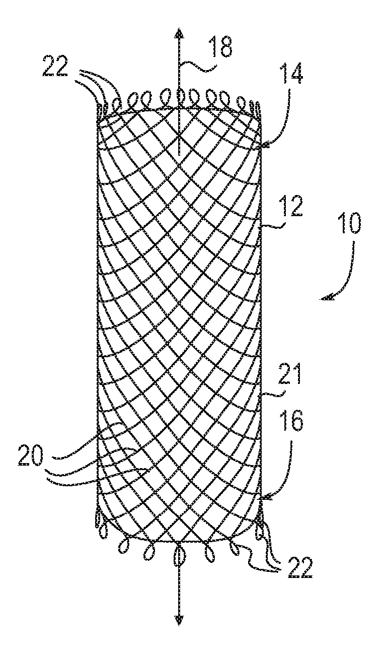
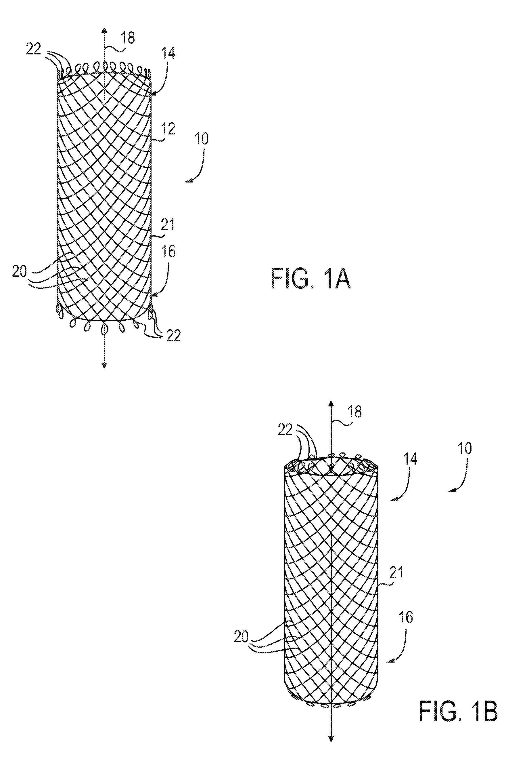
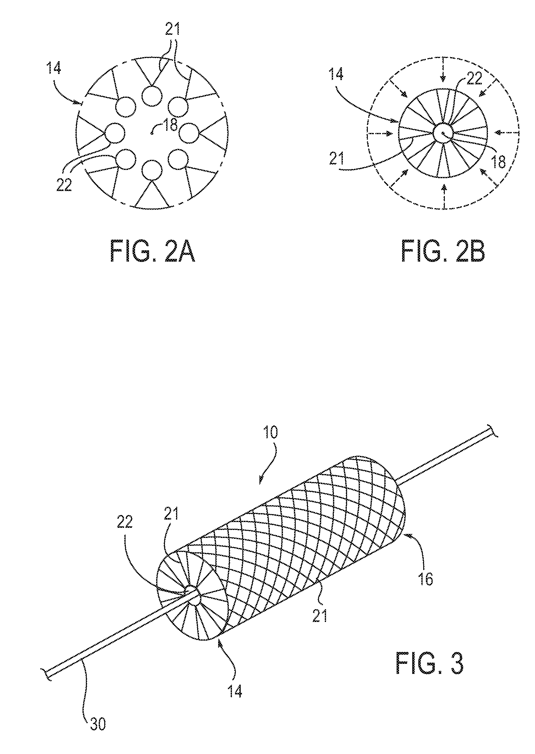
[0075]FIG. 1A illustrates an embodiment of a self-expanding stent 10 of the present invention. The stent 10 comprises an expandable body 12 having a generally tubular shape extending between a first end 14 and a second end 16 along a longitudinal axis 18. The expandable body 12 is transitionable between an unexpanded state, having a reduced cross-sectional diameter, and an expanded state having a greater cross-sectional diameter. In each of the described embodiments, the expandable body 12 is comprised of frame 21 formed from a plurality of wires 20 braided into a mesh or weave or formed by other methods, such as laser cutting, chemical etching or photo etching, to name a few. One or more portions of the frame 21 may be comprised of a superelastic material, a shape-memory material, Nickel-Titanium (Nitinol®), platinum, cobalt chromium, stainless steel, tantalum, gold, tungsten, platinum iridium, ePTFE, a polymer, a metal, Drawn Filled Tube (Nitinol® tube having a core volume filled ...


PUM


Abstract

Devices, systems and methods are provided for stenting body lumens. In particular, stents are provided which are advanceable directly over a guidewire and expandable within a target location of a body lumen by retraction of the guidewire and / or by releasing constraining element(s) disposed around at least a portion of the stent. Typically the constraining element(s) have the form of one or more bands or layers of material which hold the stent in an unexpanded configuration. These stent designs allow delivery to a body lumen without the need for a number of additional devices which are typically used in the delivery of conventional stents, thereby reducing the profile of the stent during delivery, increasing the flexibility of the stent during delivery to allow passage through more tortuous pathways, and allowing the delivery of branched or otherwise connected stents to body lumens, such as branched lumens.

Description

CROSS-REFERENCES TO RELATED APPLICATIONS [0001] This application claims the benefit and priority of U.S. Provisional Patent Application No. 60 / 655,525 (Attorney Docket TSU-001), filed Feb. 23, 2005, the full disclosure of which is hereby incorporated by reference for all purposes.STATEMENT AS TO RIGHTS TO INVENTIONS MADE UNDER FEDERALLY SPONSORED RESEARCH OR DEVELOPMENT [0002] NOT APPLICABLE REFERENCE TO A “SEQUENCE LISTING,” A TABLE, OR A COMPUTER PROGRAM LISTING APPENDIX SUBMITTED ON A COMPACT DISK [0003] NOT APPLICABLE BACKGROUND OF THE INVENTION [0004] A stent comprises a small metal coil, slotted tube, mesh or scaffold structure that is placed in a body lumen, such as the vasculature, to support the lumen wall. Such support may be desired in a variety of applications. For example, stents may be used following percutaneous transluminal coronary angioplasty (PTCA) procedures. In PTCA procedures, a catheter having a small balloon disposed near its distal end is advanced through th...

Claims


Application Information

Patent Timeline
Patent Type & Authority Applications(United States)
IPC IPC(8): A61F2/06A61F2/82A61F2/90
CPCA61F2/90A61F2/954A61F2/97A61F2002/065A61F2002/067A61F2230/0095A61F2002/9505A61F2002/9511A61F2250/0071A61F2210/0076A61F2230/0013A61F2002/823
Inventor DIECK, MARTIN S.MARTIN, BRIAN B.
Owner TSUNAMI INNOVATIONS
Why Eureka
Try Eureka