Application level interface to network analysis tools

a network analysis and application level technology, applied in the field of network analysis, can solve the problems of daunting and often seemingly impossible tasks of driving a conventional network simulator, and achieve the effects of facilitating the creation and/or modification of input, and facilitating the use of application layer parameters and application layer logi

Active Publication Date: 2006-08-24
RIVERBED TECH LLC
View PDF4 Cites 26 Cited by
  • Summary
  • Abstract
  • Description
  • Claims
  • Application Information

AI Technical Summary

Benefits of technology

[0011] Due to the dynamic nature of application, it is an objective of this invention to ease the task of creating and / or modifying the input data to a network simulator, and particularly the messages that are to be initiated at the nodes. It is a further objective of this invention to facilitate the creation and / or modification of the input to a network simulator from an application layer perspective. It is a further objective of this invention to integrate the viewing of results from one simulation with the creation and / or modification of input for a subsequent simulation.
[0012] These objectives, and others, are achieved by providing a user interface to a network simulator that facilitates the use of application layer parameters and application layer logic. The user interface is configured to allow the user to define the input in a graphic form, or a text / programming form, or a combination of both. Preferably, the user interface provides common graphic forms for both inputting the data to the simulator as well as for displaying the resultant data from the simulator, thereby easing the progression from the analysis of output from one simulation to the generation of new input for a subsequent simulation.

Problems solved by technology

The application developer, on the other hand, deals with the operation of the application at the application protocol layer, and the creation and / or modification of the transport protocol input data to drive a conventional network simulator can be a daunting, and often seemingly impossible task.

Method used


Image

  • Application level interface to network analysis tools
  • Application level interface to network analysis tools
  • Application level interface to network analysis tools

Examples


example embodiments

[0056] Example Embodiments

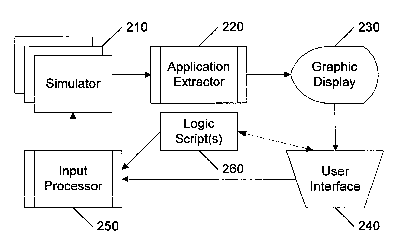
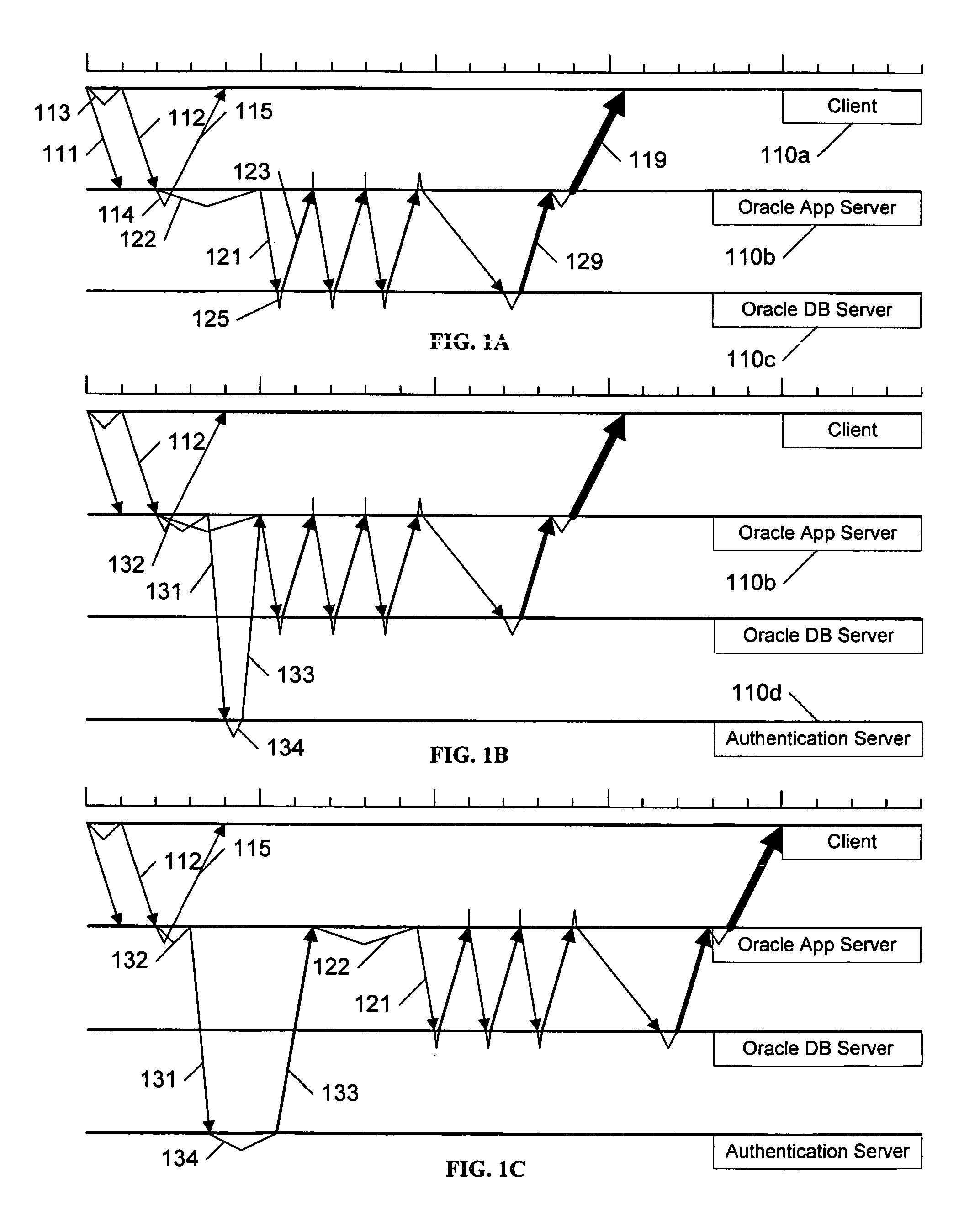
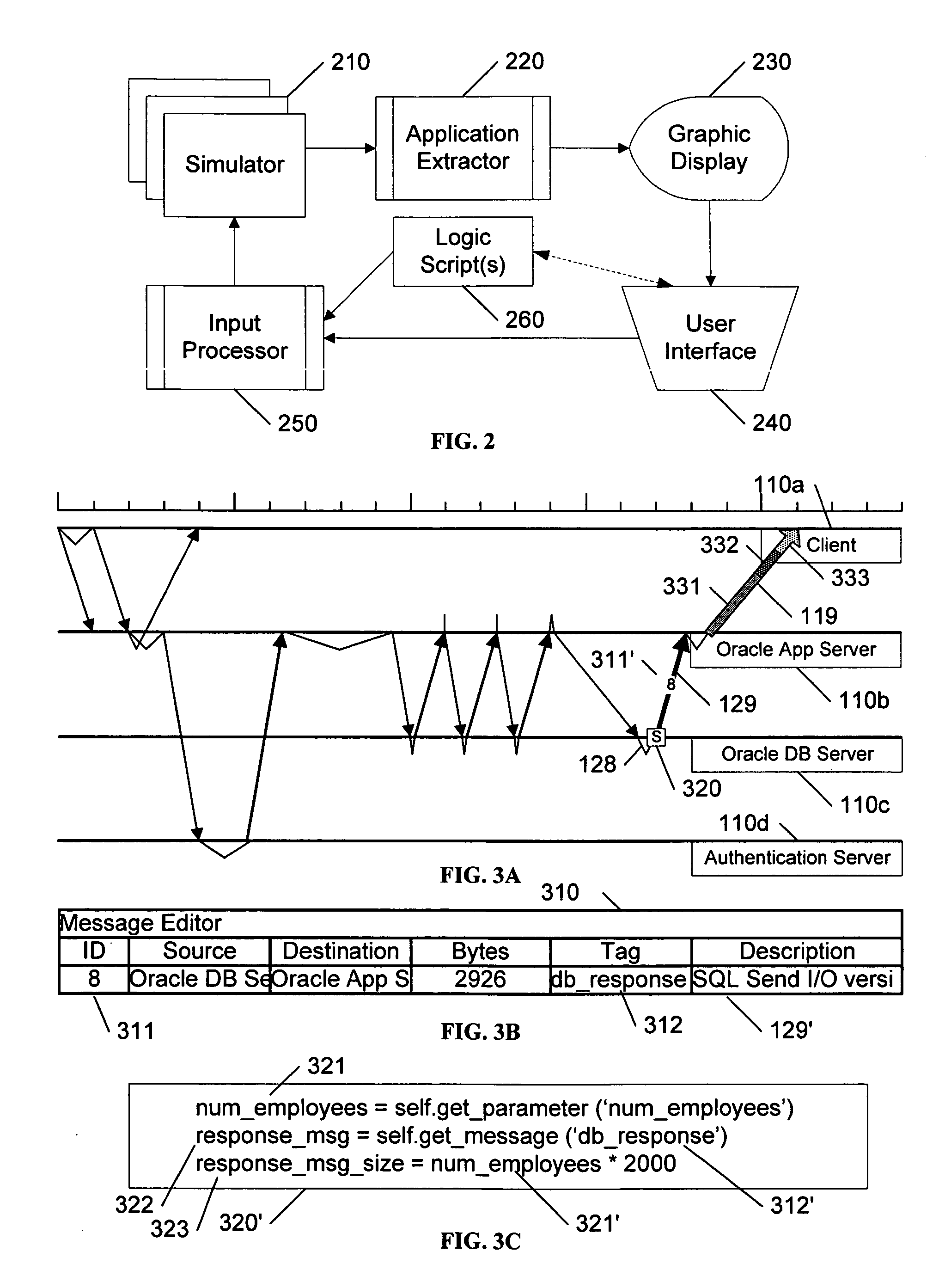
[0057] In FIG. 1A, the three example tiers include a client 110a, an application server 110b, and a database server 110c, and illustrate a series of exchanges, such as might occur when a client 110a requests information from a database 110c, via commands sent to a server 110b. The client 110a initiates the transaction via a series of messages 111, 112 to the server 110b. In response to these messages 111, 112, the server 110b sends a message 115 to the client 110a, acknowledging receipt of the messages 111, 112, and also sends a message 121 to the database server 110c, requesting the data corresponding to the request from the client 110a. Thereafter, the database server 110c exchanges a number of messages 123-129 to effect the data transfer. The application server 110b packages the received data and communicates it to the client 110a via one or more messages 119.

[0058] The illustrated messages 111-129 may have been extracted from a simulation of a network ...


PUM


Abstract

A user interface to a network simulator facilitates the use of application layer parameters and application layer logic. The user interface is configured to allow the user to define the input in a graphic form, or a text/programming form, or a combination of both. Preferably, the user interface provides common graphic forms for both inputting the data to the simulator as well as for displaying the resultant data from the simulator, thereby easing the progression from the analysis of output from one simulation to the generation of new input for a subsequent simulation.

Description

[0001] This application claims the benefit of U.S. Provisional Patent Application 60 / 654,073 filed 18 Feb. 2005.BACKGROUND AND SUMMARY OF THE INVENTION [0002] This application relates to the field of network analysis, and in particular to a user interface to a network simulation system that facilitates an interactive analysis of the expected performance of an application when deployed on a network. [0003] Network simulators are commonly used to determine the expected performance of a network under a variety of simulated conditions. The interconnection of elements forming a network is modeled, and hypothetical traffic patterns are provided to the model to determine and / or estimate how the modeled network will perform under these traffic conditions. Alternative interconnections and / or configurations of the elements can also be modeled, to perform a “what-if?” analysis, or to diagnose real or assumed problems in the network. [0004] Generally, networks are modeled down at the transport ...

Claims


Application Information

Patent Timeline
Patent Type & Authority Applications(United States)
IPC IPC(8): G06F13/10G06F9/45
CPCH04L41/22H04L41/145
Inventor MALLOY, PATRICK J.COHEN, ALAINBARDON, WILLIAM E. JR.DUNN, ANTOINEGEHL, RYANGUPTA, NISHANTLAVANNIS, MAHESHSTROHM, JOHNSUKUMAR, PRASANNA
Owner RIVERBED TECH LLC
Why Eureka
Try Eureka