
Reactor for performing a steam reforming reaction and a process to prepare synthesis gas

a technology of steam reforming reaction and reactor tube, which is applied in the direction of combustible gas production, chemical apparatus and processes, chemical/physical processes, etc., can solve the problems of less heat exchange, less efficient operation, and exterior surface corrosion of the reactor tub

Inactive Publication Date: 2006-08-31
SHELL OIL CO
View PDF7 Cites 10 Cited by
  • Summary
  • Abstract
  • Description
  • Claims
  • Application Information

AI Technical Summary

Benefits of technology

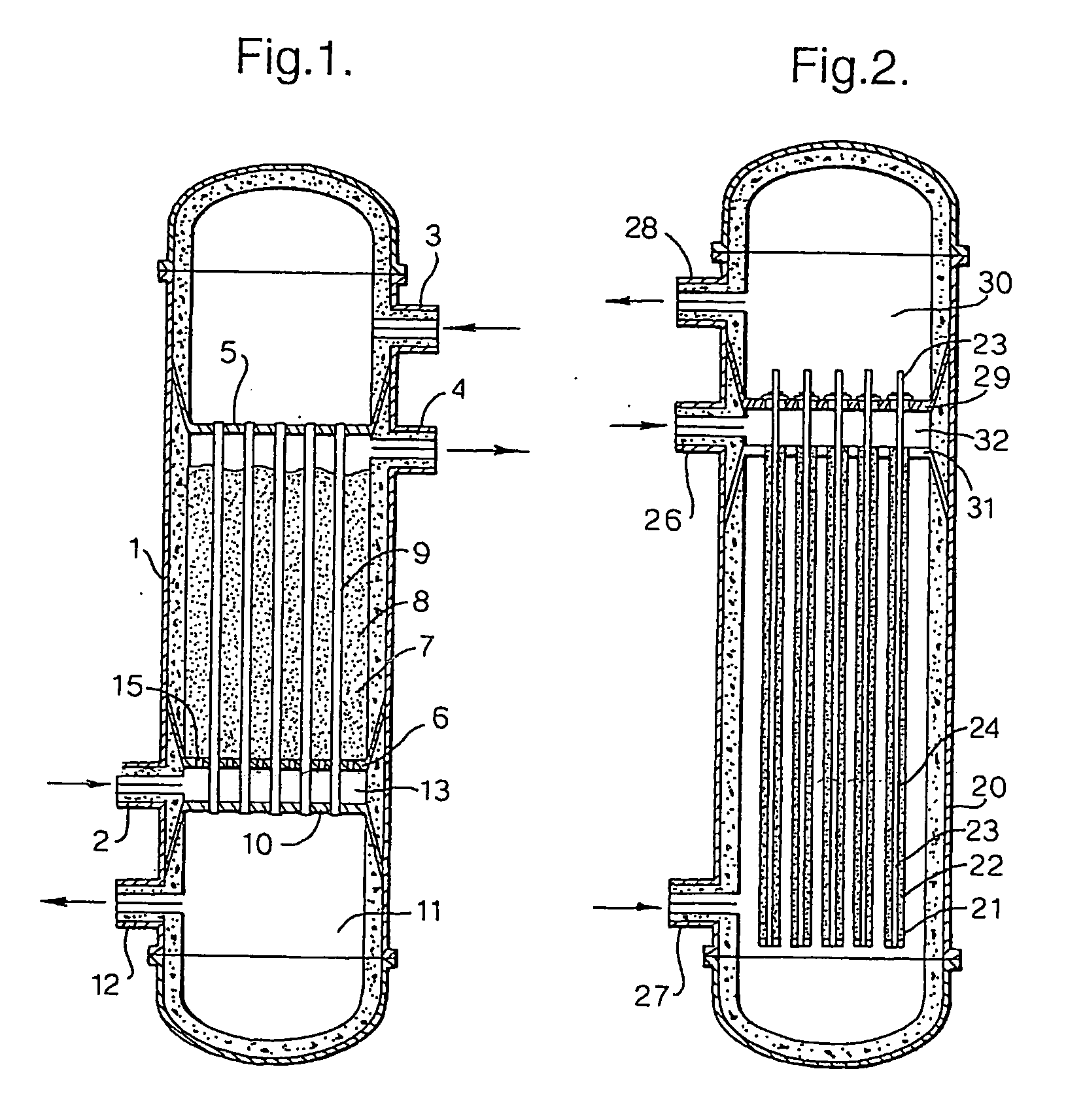
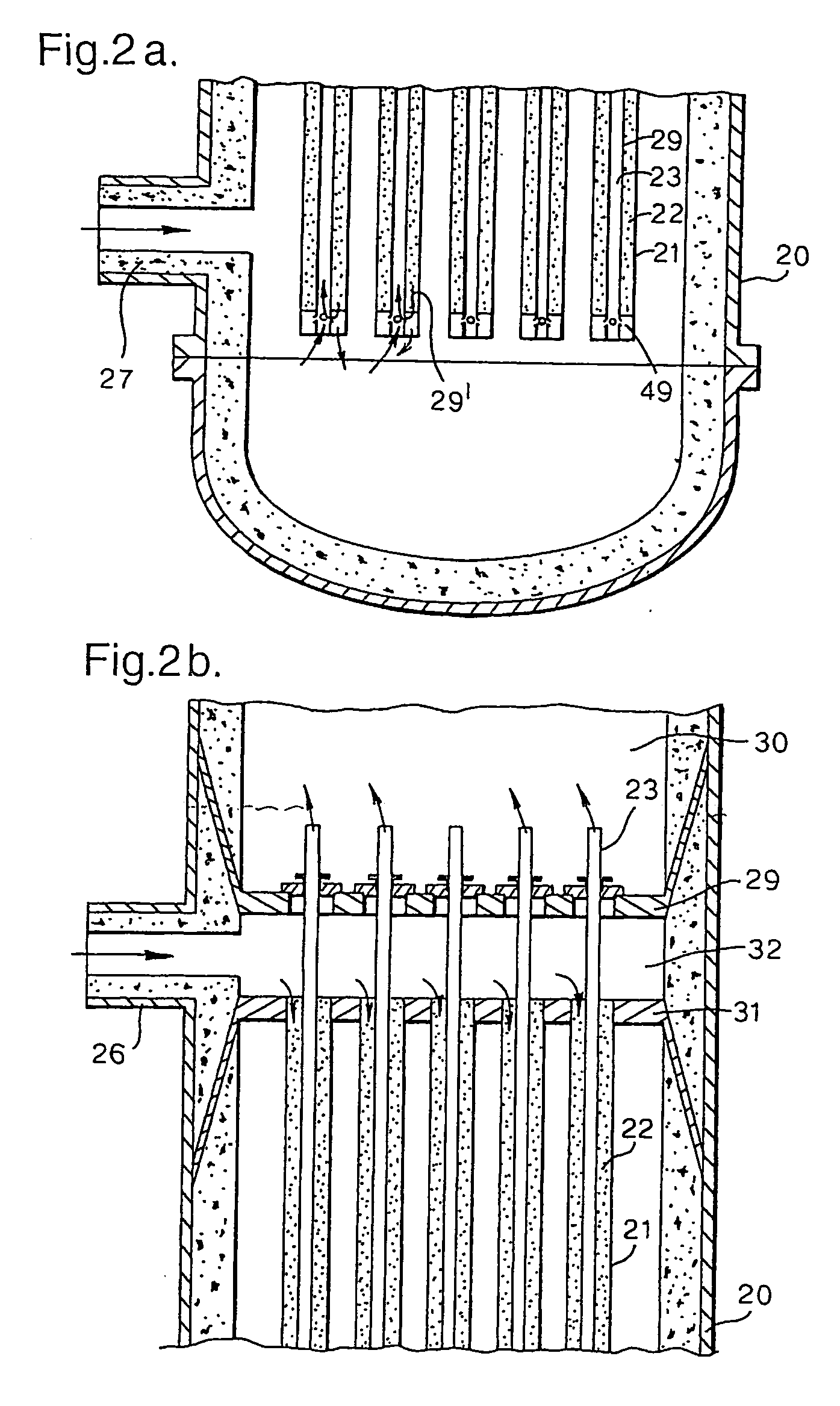
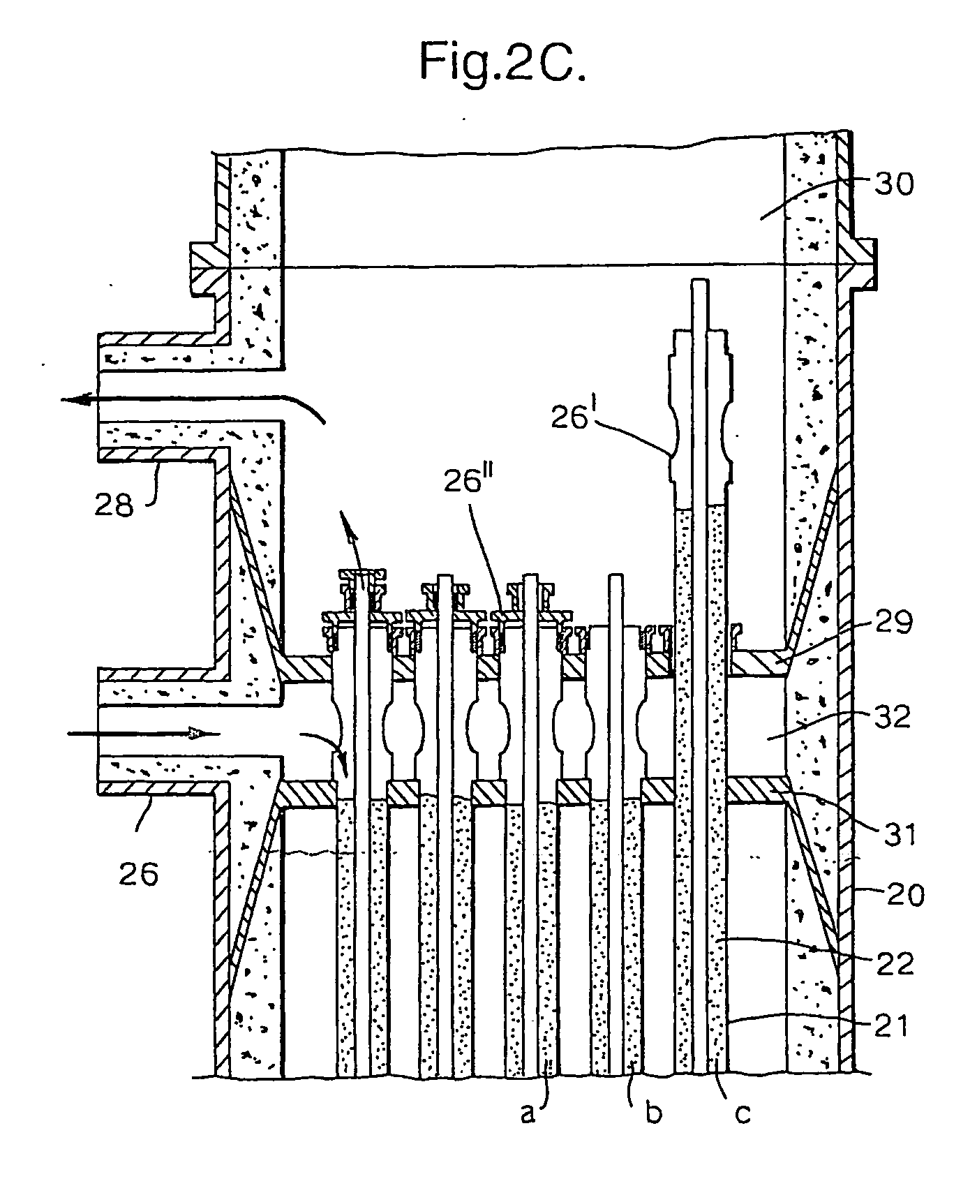
[0030] In the reactor as shown in part or all of the product gas of the steam reforming reaction is also passed through the elongated passageways. This is advantageous when the hot gaseous mixture is the effluent of the partial oxidation reaction preferably having a steam to carbon ratio of less than 0.5. By combining these streams the steam to carbon ratio of the resulting mixture flowing in the passageways (23) will be higher and thereby minimizing metal dusting corrosion within the passageways (23).

Problems solved by technology

A disadvantage of the known reactor vessel design is that fouling may occur at the exterior surface of the reactor tubes.
This fouling will result in a less favourable heat exchange between hot gas and the catalyst bed and in time result in a less efficient operation.
Fouling is especially a problem when the hot effluent of a partial oxidation reaction is used.
However the soot present in this effluent will cause the above fouling problems and for this reason no commercial applications directed to the combined process of steam reforming and partial oxidation such as described in DE-A-3345088 has been developed according to our knowledge at time of filing.

Method used


Image

  • Reactor for performing a steam reforming reaction and a process to prepare synthesis gas
  • Reactor for performing a steam reforming reaction and a process to prepare synthesis gas
  • Reactor for performing a steam reforming reaction and a process to prepare synthesis gas

Examples


example 1

[0073] To a steam reformer reactor according to FIG. 2 natural gas and steam are fed in a steam to carbon ratio of 0.75. Also a hot effluent of a partial oxidation reactor is fed via 27 to said reactor. The mass flows, temperatures and resultant product streams are described in Table 1.

example 2

[0074] Example 1 is repeated except that the steam to carbon ratio of the feed to the CSR reactor of FIG. 2 was equal to 1.

example 3

[0075] In this example the effluent of the reactor tubes was first fed to the partial oxidation reactor as is illustrated in FIG. 4 (line 55). No catalyst bed 53 was present in the reactor 51.

EXAMPLE 1Parallel operation - steam to carbon ratio of 0.75Effluent of thepartial oxidationGas leaving theFeed to theFeed to the reac-entering thereactor tubes 21partial oxidationtor of FIG. 2 viareactor of FIG. 2of the reactor ofreactorinlet (26).via (27)flow rateflow rateflow rateflow rateStream namemol %mol %mol %mol %Componentkmol / h(dry)kmol / h(dry)kmol / h(dry)kmol / h(dry)Hexane00.0000.0000.0000.00Pentane00.0000.0000.0000.00Butane440.11130.1200.0000.00Propane1860.46560.5200.0000.00Ethane1,4233.524273.9400.0000.00Methane21,72753.756,52660.208221.195141.61Hydrogen6131.521841.7042,62461.6320,78664.91Carbon00.0000.0023,60434.137,17122.39MonoxideCarbon2670.663,36831.061,1491.663,28510.26DioxideNitrogen8862.192662.458861.282660.83Argon760.1900.00760.1100.00Oxygen15,20137.6000.0000.0000.00Steam00.0...


PUM

PropertyMeasurementUnit
velocityaaaaaaaaaa
velocityaaaaaaaaaa
molar ratioaaaaaaaaaa

Abstract

A reactor vessel for performing a steam reforming reaction having a vessel inlet for natural gas and steam; a vessel inlet for a hot gaseous medium; a vessel outlet for the steam reforming product; and a reactor space which is a bed of steam reforming catalyst, which reactor space inlet is fluidly connected to the inlet for natural gas and steam and at its outlet end fluidly connected with the outlet for the gaseous product; wherein inside the catalyst bed a passageway is provided fluidly connected to the vessel inlet for the hot gaseous medium for passage of hot gaseous mixture counter currently to the flow of reactants in the catalyst bed.

Description

FIELD OF THE INVENTION [0001] The invention is directed to a reactor vessel for performing a steam reforming reaction starting from a natural gas feedstock. The invention is also directed to a process to prepare a mixture comprising carbon monoxide and hydrogen from a carbonaceous feed by performing a partial oxidation reaction and an endothermic steam reforming reaction. BACKGROUND OF THE INVENTION [0002] EP-A-168892 describes an endothermic steam reforming reaction, which is carried out in a fixed bed situated in at least one pipe in which a temperature of between 800 and 950° C. is maintained by routing at least part of the hot product gas from a partial oxidation reaction along the pipe(s). According to this publication the combined partial oxidation and endothermic production of synthesis gas result in a better yield of synthesis gas, an increased H2 / CO ratio, a lower usage of oxygen per m3 of synthesis gas product obtained and a lower capital cost of the plant for the producti...

Claims


Application Information

Patent Timeline
Patent Type & Authority Applications(United States)
IPC IPC(8): B01J8/00B01J8/04B01J8/06C01B3/38
CPCB01J8/008C01B2203/82B01J8/0496B01J8/062B01J8/067B01J2208/00309B01J2208/00495B01J2208/00504C01B3/382C01B3/384C01B2203/00C01B2203/0233C01B2203/0244C01B2203/025C01B2203/0255C01B2203/0405C01B2203/042C01B2203/062C01B2203/0844C01B2203/1052C01B2203/1058C01B2203/1064C01B2203/1082C01B2203/1241C01B2203/141C01B2203/142C01B2203/143C01B2203/148B01J8/0449B01J8/00B01J8/06C01B3/38
Inventor BERGGREN, WOUTER DETLOFVAN DONGEN, FRANCISCUS GERADUSTIO, THIAN HOEYZUIDEVELD, PIETER LAMMERT
Owner SHELL OIL CO
Learn More