Backpack for harvesting electrical energy during walking and for minimizing shoulder strain

a backpack and walking technology, applied in the direction of generators/motors, machines/engines, electric generator control, etc., can solve the problems of limiting the time soldiers can remain in the field, battery weight can become a significant issue, and the total dependence on batteries, so as to reduce the absolute vertical motion, and increase the force

Active Publication Date: 2006-08-31
LIGHTNING PACKS
View PDF25 Cites 49 Cited by
  • Summary
  • Abstract
  • Description
  • Claims
  • Application Information

AI Technical Summary

Benefits of technology

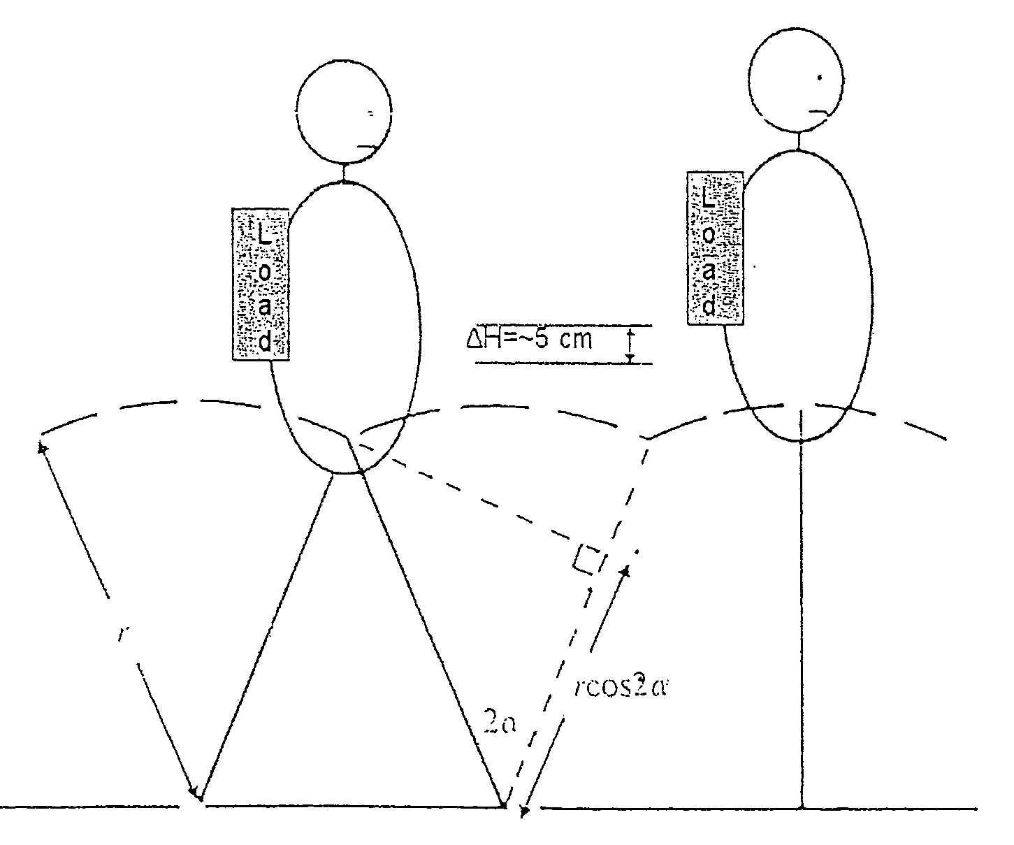
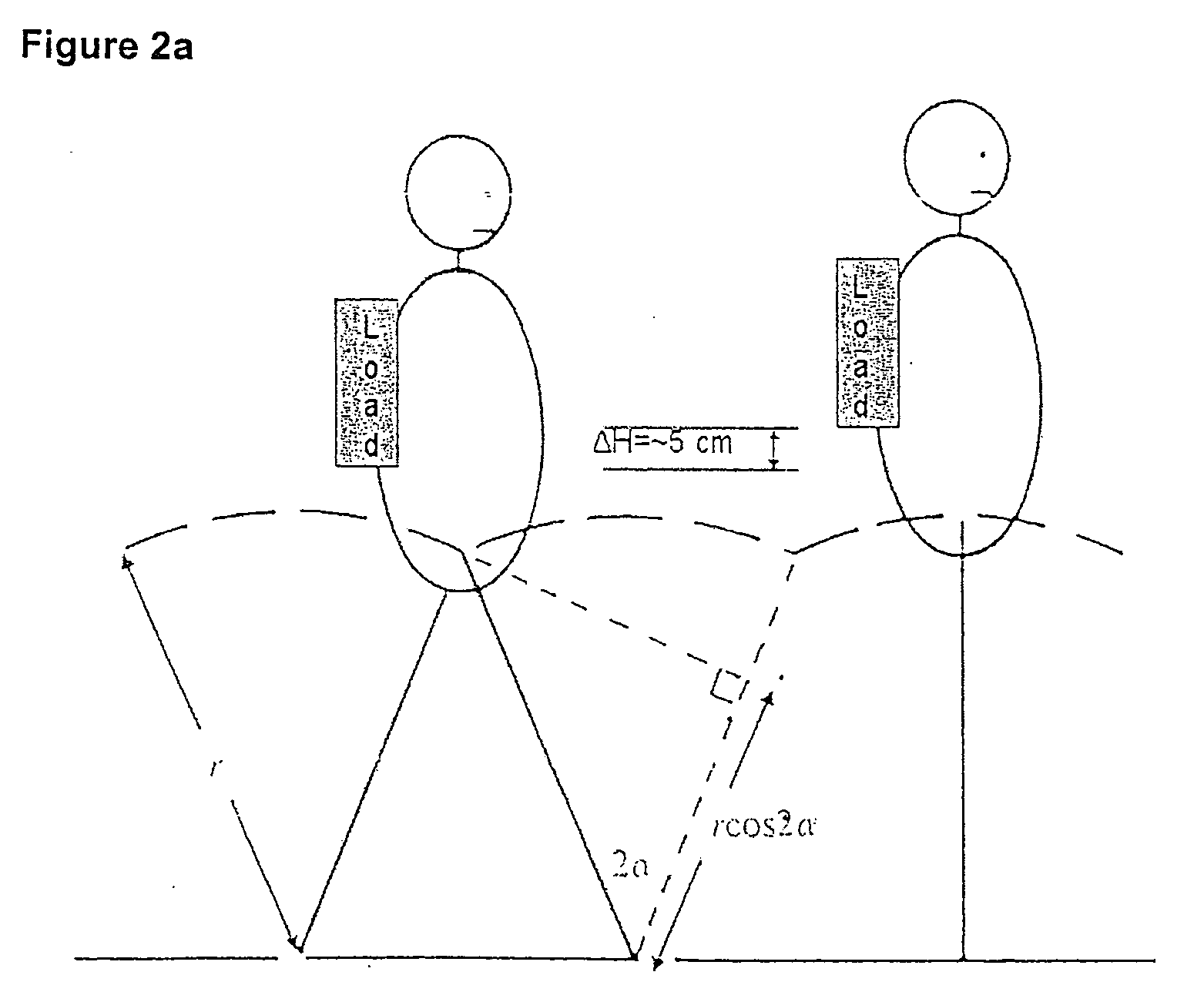
[0011] Based on a biomechanical analysis, the present inventor has developed a strategy and device (suspended-load backpack) that can produce large forceful movements. These movements, when coupled with artificial muscle energy-generating or other mechanical energy to electrical energy conversion technologies in accordance with the invention permit the generation of several watts of electrical energy during normal walking movements. The backpack is designed to permit the load to move relative to the backpack frame during walking so that the large movements between the load and the frame of the backpack during walking can be transferred to a motor through, for example, a rack and pinion gear, to convert the mechanical movement to electrical energy. The movement may also be converted to electrical energy by using an electroactive polymer (EAP) (or other artificial muscle technologies) to connect the suspended load to the frame. These large movements of the load also reduce the absolute vertical motion of the load with respect to the ground. In particular, because the hip (and thus the pack frame) go up a down a good deal during walking (and even more during running) with a fixed load, large accelerations are necessary that exert large forces back on the shoulders and other parts of the body. The large relative movement between the frame and the load noted above reduces the absolute vertical excursion of the load and thus the locomotion induced increase in force. To facilitate this function, such designs not only allow the load to make large movements but to move in a controlled fashion. This prevents the wearer from losing his or her balance as the load moves up and down along the backpack frame, and extends human performance by permitting the wearer to run with heavy loads.

Problems solved by technology

Total dependence on batteries is problematic because short battery lifespan requires larger batteries, and battery weight can become a significant issue.
In the case of the military, carrying batteries becomes a backbreaking load (packs weigh in excess of 80 lbs) which limits the time soldiers can remain in the field.
Up to now, attempts to extract such energy have been extremely limited in terms of wattage (i.e., 10-20 milliwatts).
Unfortunately, the only place that is relatively accessible, the foot, is a relatively poor location for extracting mechanical energy because very little mechanical work is done at the foot during locomotion.
However, Pelrine et al. offer no suggestions as to how to design such a backpack device.
Pelrine et al. also do not recognize that a suspended load leads to controlled up / down movement and reduced stress on the wearer's shoulders as well as on the rest of his or her body.
Heavy backpack loads are known to lead to spinal injuries, particularly in children.
Of course, this approach is quite expensive.
Such designs are problematic since they do not provide much assistance when the user has to cross grass or more difficult terrain.
Unfortunately, Duckworth did not address the physics of walking or running with a backpack and simply built classic shock absorbers.
Their springs are too short in length and too stiff to permit the large relative movements between the frame and the load which are necessary to keep the load relatively still with respect to the ground.
Accordingly, rapid movement with the backpack taught by Duckworth would cause the generation of a very large force which would limit the relative movement between the load and the frame resulting in high shoulder loading as well as potentially causing the wearer to lose his or her balance.

Method used


Image

  • Backpack for harvesting electrical energy during walking and for minimizing shoulder strain
  • Backpack for harvesting electrical energy during walking and for minimizing shoulder strain
  • Backpack for harvesting electrical energy during walking and for minimizing shoulder strain

Examples


first embodiment

[0066]FIGS. 4 and 5 illustrate a rear perspective view of a suspended-load backpack 10 in accordance with the invention. As illustrated, backpack 10 includes a frame 20 including vertical rods 22 and horizontal bars 24. In an illustrative embodiment, rods 22 are made of hardened chrome plated shafts having ½ inch diameters while bars 24 are made of aluminum. Frame 20 supports a suspended load 30 which may be in the form of a box or satchel connected to a load support structure or (e.g., aluminum) plate 40 suspended with respect to the frame 20. In the embodiment of FIGS. 4 and 5, the load support structure 40 is supported with respect to frame 20 in the vertical direction by extension springs 50 (e.g., nickel plated steel with 2:1 extension and 5.2 lbs / in. spring constant) that have spring constants selected to support the desired load rating for the suspended load 30. A fourth identical extension spring pulls down on plate 40, thereby providing a restoring force. Although three spr...

second embodiment

[0069]FIG. 7 illustrates a mechanism for transferring mechanical movement to a DC servo motor 120 where the lever crank mechanism is replaced by a rack 140 connected to load support structure 40 and a corresponding pinion gear 150 connected directly or through gear linkages to DC servo motor 120. As in the embodiment of FIG. 6a, the rack 140 may fold away from the pinion gear 150 to facilitate access to the pinion gear 150 for manual cranking of the DC servo motor 120, as when the user is resting. FIG. 8a illustrates the mechanism of FIG. 7 in more detail. As illustrated, the up / down movement of the rack 140 with respect to the pinion gear 150 turns gears 114, 116, 118, and 119 so as to transfer energy to DC servo motor 120. As shown in FIG. 8b, the output of DC servo motor 120 is provided to an electronics charging unit 400 where it is rectified by a rectifier 122 and filtered by a capacitive filter 124 before being provided to a battery charger 126 for recharging batteries in batt...

third embodiment

[0071]FIG. 10 illustrates a mechanism for transferring mechanical movement to an electric motor unidirectionally using two racks 170 and 175 and two sets pf pinion gears 180, 195 and 185, 190, one rack and pinion gear for upward movement (rack 175 and pinion gears 185, 190) and one rack and pinion gear for downward movement (rack 170 and pinion gears 180, 195). Better electricity generation may be achieved by providing unidirectional movement of the DC servo motor 120. As illustrated, the two racks 170 and 175, two pinion gears180 and 190, and two free wheels 205, 208 (with opposite polarities) are attached to the motor gears (FIG. 8b) to facilitate clockwise cranking of the motor gear both as the suspended load 30 rises and as suspended load 30 falls during walking. As illustrated, one rack 170 drives the motor gear on the way up and the other rack 175 drives the motor gear on the way down. When coupled to a fly wheel 200 to drive the motor gear in one constant direction, this move...


PUM


Abstract

A suspended-load backpack designed to permit the load to move relative to the backpack frame during walking and running so that the large movements between the load and the frame of the backpack reduce the fluctuations of absolute vertical motion of the load. Because the hip (and thus the pack frame) go up a down a good deal during walking, a large relative movement between the frame and the load reduces the absolute excursion of the load. This movement may be, in turn, transferred to a motor through, for example, a rack and pinion gear, to convert the mechanical movement to electrical energy. The movement may also be converted to electrical energy by using an electroactive polymer (EAP) to connect the suspended load to the frame. Such designs allow the load to move in a controlled fashion to prevent the patient from losing his or her balance as the load moves up and down along the backpack frame. Such movement of the suspended-load relative to the frame also reduces the forces on the wearer's shoulders while walking or running, thus reducing the likelihood of orthopedic injury.

Description

CROSS-REFERENCE TO RELATED APPLICATIONS [0001] The present application claims priority to U.S. Provisional Patent Application Ser. No. 60 / 455,477, filed Mar. 17, 2003, the contents of which are incorporated herein by reference.GOVERNMENT SUPPORT [0002] The present invention was supported by the National Institutes of Health under Grant Nos. AR38404 and AR46125 and certain aspects may be supported by the Office of Naval Research under ONR Grant No. N000140310568. The government may have certain rights in the invention.FIELD OF THE INVENTION [0003] The present invention relates to ergonomically designed backpacks and, in particular, to backpacks that permit the wearer to generate electrical energy from the mechanical energy created by movement of the backpack during walking. BACKGROUND OF THE INVENTION [0004] Man has become more dependent on technology in all arenas of life. The ubiquitous use of mobile technologies requires that constant electrical power, presently provided by batter...

Claims


Application Information

Patent Timeline
Patent Type & Authority Applications(United States)
IPC IPC(8): H02K7/18F03G7/08F02B63/04A45FA45F3/04A45F3/06A45F3/08F03G3/02F03G5/06H02P9/04
CPCA45F3/06A45F3/08F03G5/06H02N2/18Y10S310/80
Inventor ROME, LAWRENCE C.
Owner LIGHTNING PACKS
Why Eureka
Try Eureka