Electric rotating machine
a rotating machine and electric technology, applied in the direction of magnetic circuit rotating parts, synchronous motors, magnetic circuit shape/form/construction, etc., can solve the problems of pulsation, worse power factor, loss of one of the advantages of small coil ends incidental to concentrated winding, etc., and achieve high productivity and efficient operation
- Summary
- Abstract
- Description
- Claims
- Application Information
AI Technical Summary
Benefits of technology
Problems solved by technology
Method used
Image
Examples
embodiment 1
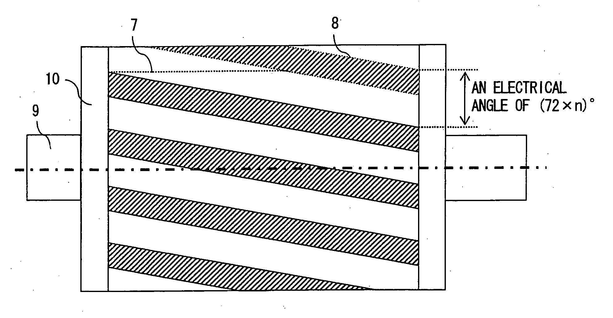
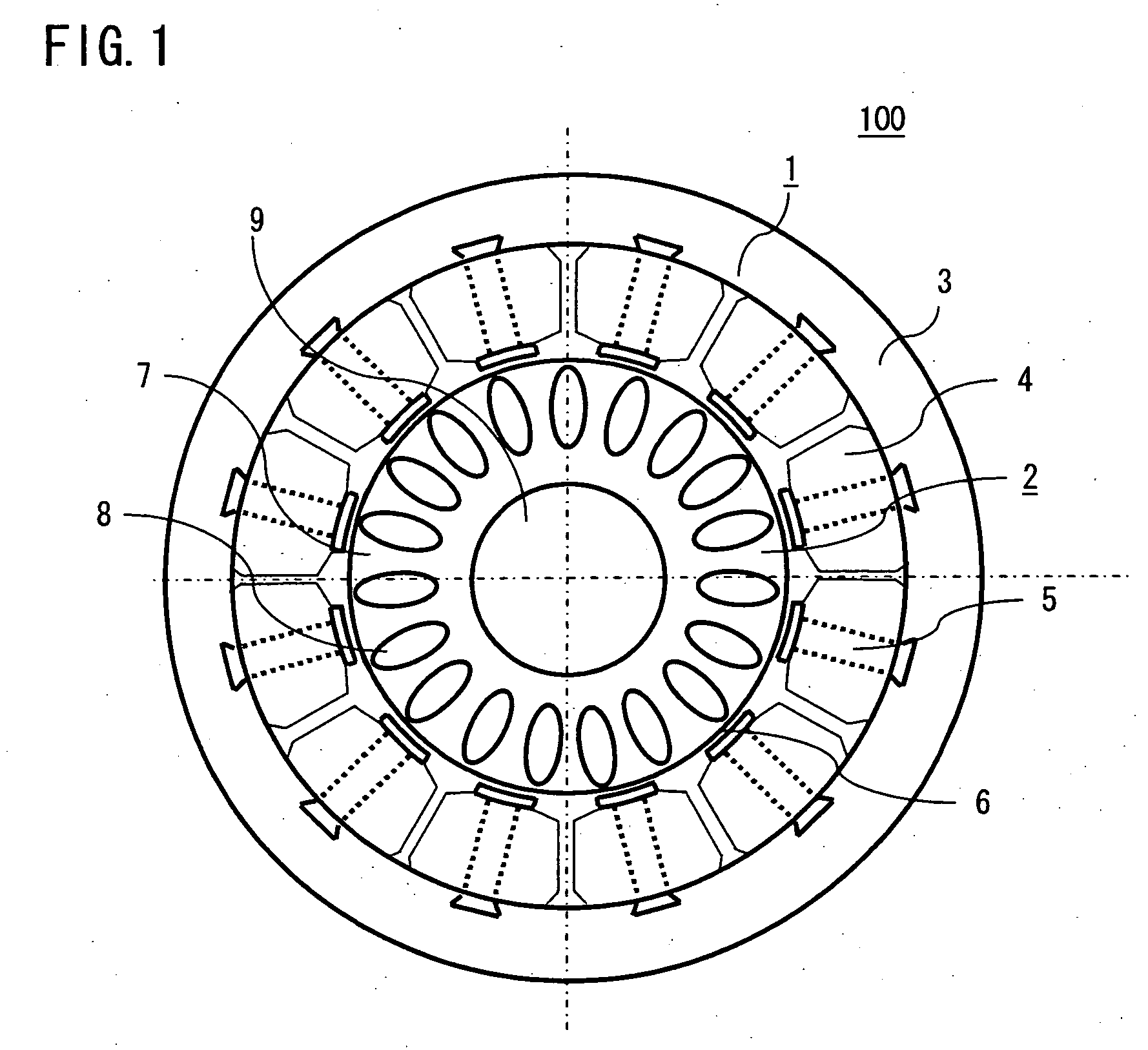
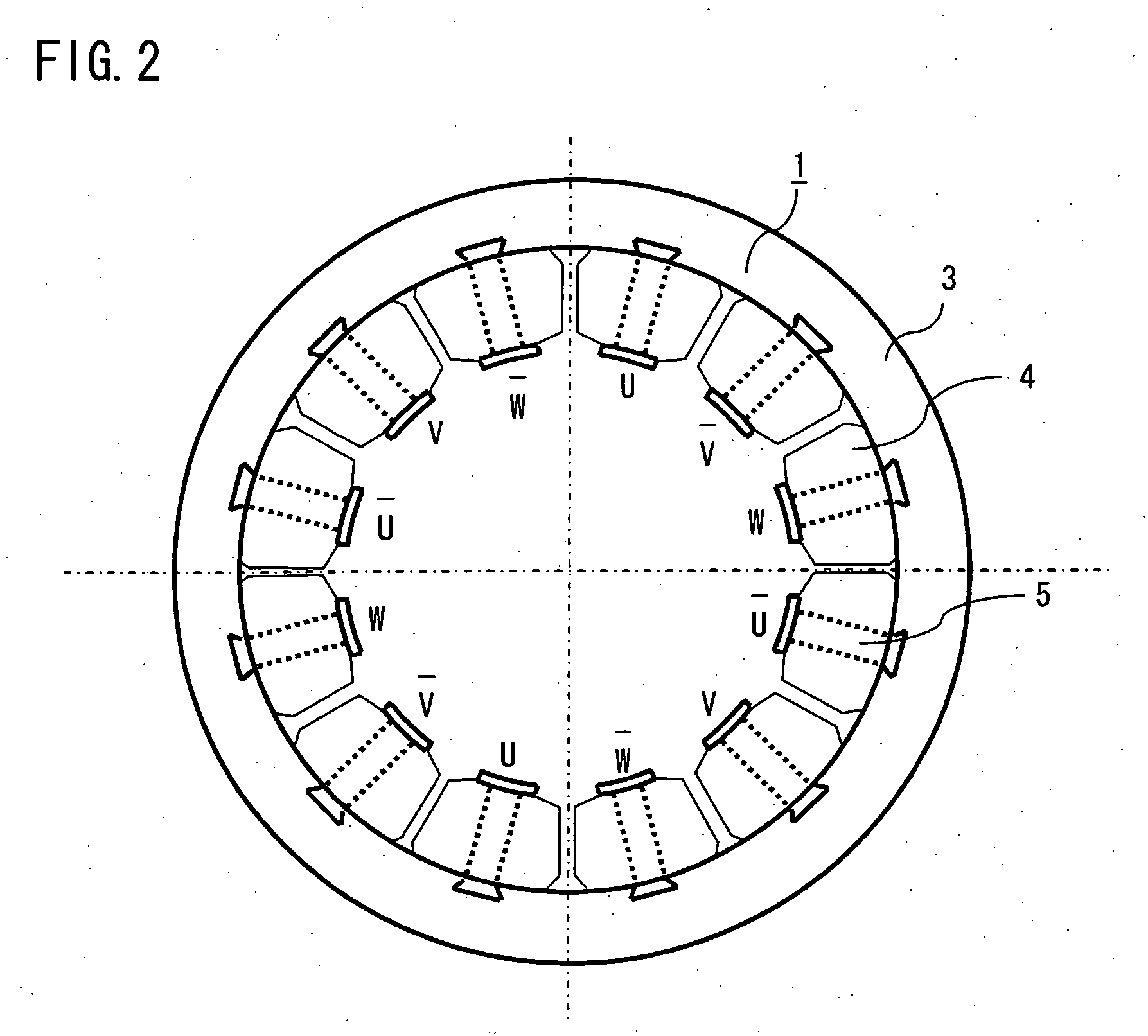
[0023]FIG. 1 is a cross sectional view showing an electric rotating machine, particularly a three-phase concentrated winding induction motor according to a first embodiment of the invention. With reference to FIG. 1, a three-phase concentrated winding induction motor 100 is formed of a stator 1 and a rotor 2. The stator 1 is manufactured by integrally forming a core back 3 that is made by laminating, e.g., an electromagnetic steel plate, and portions in each of which a tooth 5 that is likewise made by laminating, e.g., an electromagnetic steel plate is wound with a coil 4 in a concentrated manner. As shown in FIG. 2, the coils 4 that are wound on each of the teeth 5 are connected to three-phase power supply (U-phase, V-phase, W-phase) respectively, and wound so as to produce a rotating magnetic field to be connected.
[0024] The rotor 2 includes a rotor core 7 that is made by laminating, e.g., an electromagnetic steel plate, and a secondary conductor 8 that is formed by, e.g., alumin...
embodiment 2
[0033] A resistance R1 of a distributed winding induction machine can be calculated with the following expression (3) letting a length of a coil (copper wire) L and a sectional area of the coil Ac: R1=ρLAC(3)
[0034] Letting a coil length per turn L1, the above L is obtained with the following expression (4) using the number of turns n and the number of slots Ns in each phase:
L=L1nNs (4)
[0035] Letting an external diameter of the stator Φd, a coil diameter 0.8Φd and the number of poles p, a coil length LE of one coil end portion of the distributed winding induction machine can be calculated with the following expression (5): LE=0.8πϕdp×π2(5)
[0036] Letting an entire slot area As, and a space factor σ, a relation represented by the following expression (6) is established: AC=ASσNSn(6)
[0037] As a result, letting core length of the stator LC, the resistance R1 is obtained with the following expression (7): R1=ρ×2 (LC+LE) nNS×NSnASσ=2ρn2NS2ASσ(LC+0.4π2pϕd)(7)
[0038] ...
embodiment 3
[0053] As described in the foregoing first embodiment, in the concentrated winding induction motor including a concentrated winding stator having a base unit of 3 slots at 1 pole can be efficiently operated since there is no higher harmonics of magnetomotive force in the secondary or 4th order, being different from a concentrated winding stator having a base unit of 3 slots at 2 poles widely used in permanent magnet-type motors.
[0054] It is to be noted that, in case of large higher harmonics of magnetomotive force in the 5th or 7th order, the pulsation (ripple) of torque is often increased. To cope with this, according to this second embodiment, the more efficient operation of a concentrated winding induction motor is achieved by decreasing higher harmonics of magnetomotive force in the 5th order.
[0055] Higher harmonics of magnetomotive force in the 5th order has awavelength of ⅕ that of fundamental wave. To be less affected by this 5th higher harmonics of magnetomotive force, a s...
PUM
 Abstract
Description
Claims
Application Information
 - R&D
- Intellectual Property
- Life Sciences
- Materials
- Tech Scout
- Unparalleled Data Quality
- Higher Quality Content
- 60% Fewer Hallucinations
Browse by: Latest US Patents, China's latest patents, Technical Efficacy Thesaurus, Application Domain, Technology Topic, Popular Technical Reports.
© 2025 PatSnap. All rights reserved.Legal|Privacy policy|Modern Slavery Act Transparency Statement|Sitemap|About US| Contact US: help@patsnap.com


