Method for assembling a non-linear composite tube

a composite tube and non-linear technology, applied in the field of tubular assemblies, can solve the problems of restricting the exhaust flow through the tube, the tubular portions of the exhaust system that extend between the system components such as the manifold and the catalytic converter are typically non-linear, and the typical after market exhaust system cannot meet these requirements, so as to facilitate temporary mechanical alignment

Inactive Publication Date: 2006-09-07
OPPERMAN DAVID
View PDF8 Cites 12 Cited by
  • Summary
  • Abstract
  • Description
  • Claims
  • Application Information

AI Technical Summary

Benefits of technology

[0010] Briefly stated, the present invention comprises a method and hardware apparatus that facilitate temporary mechanical alignment and assembly of discrete straight tube portions and tube

Problems solved by technology

The tubular portions of an exhaust system that extend between system components such as the manifold and catalytic converter are typically non-linear because of the spatial constraints in the engine compartment and beneath the motor vehicle.
Typical after market exhaust systems cannot meet these requirements, in part, because they are produced from steel tubing formed on inexpensive compression-type tube benders.
Compression-type tube benders significantly reduce the cross-sectional area of the tube in the area of a bend, resulting in an undesirable restriction of the exhaust flow through the tube.
After market exhaust systems are also generally unattractive in appearance an

Method used


Image

  • Method for assembling a non-linear composite tube
  • Method for assembling a non-linear composite tube
  • Method for assembling a non-linear composite tube

Examples


Embodiment Construction

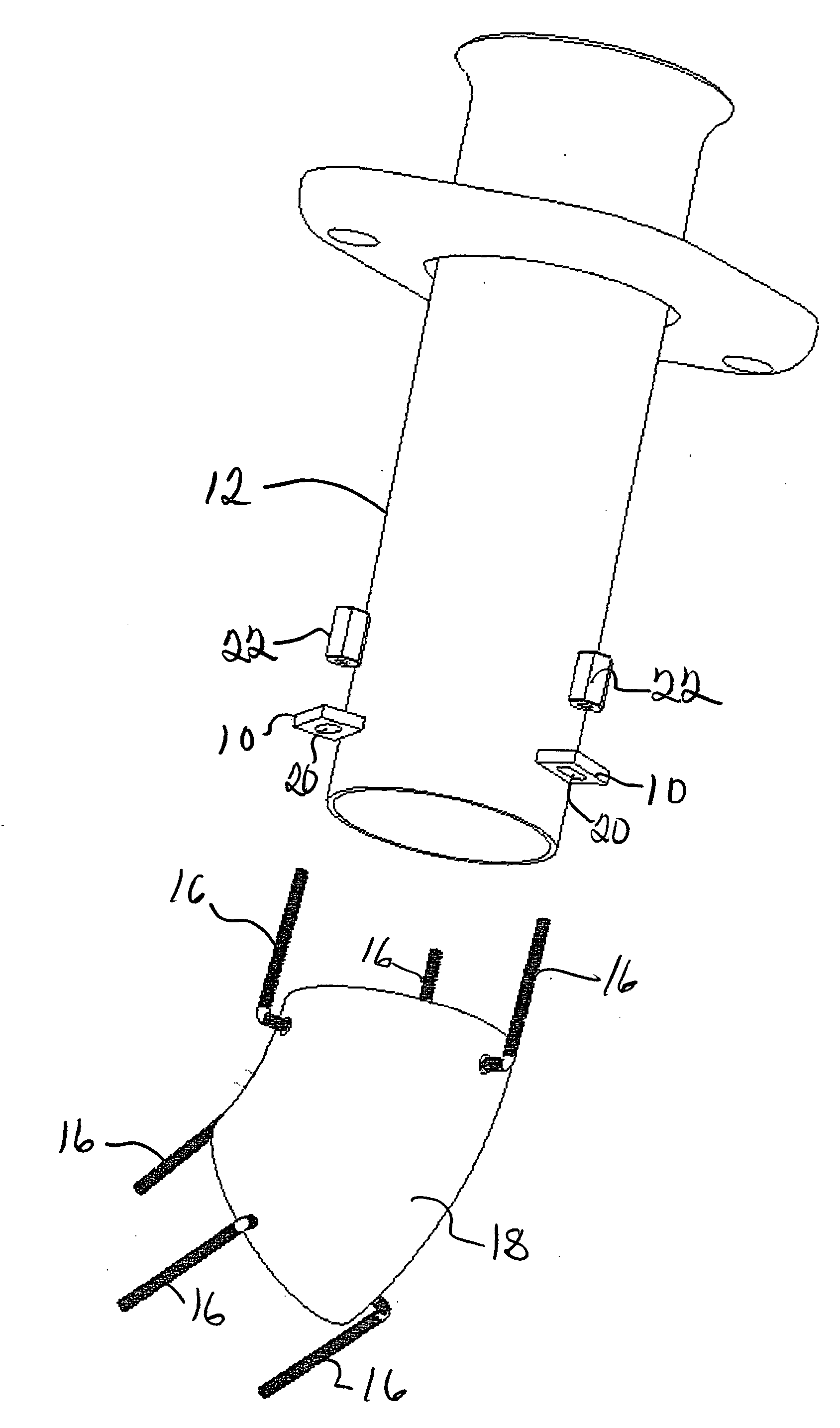
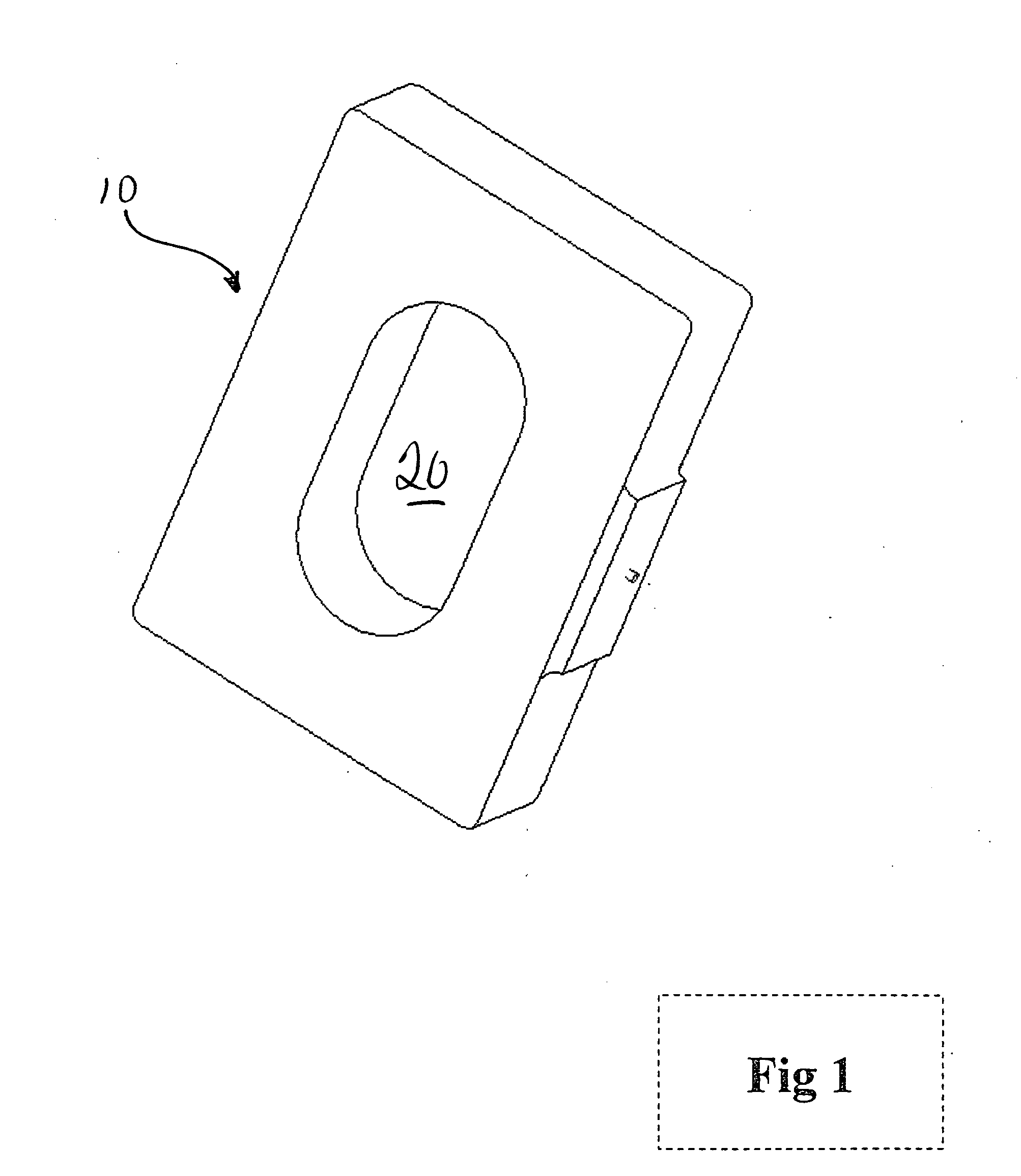
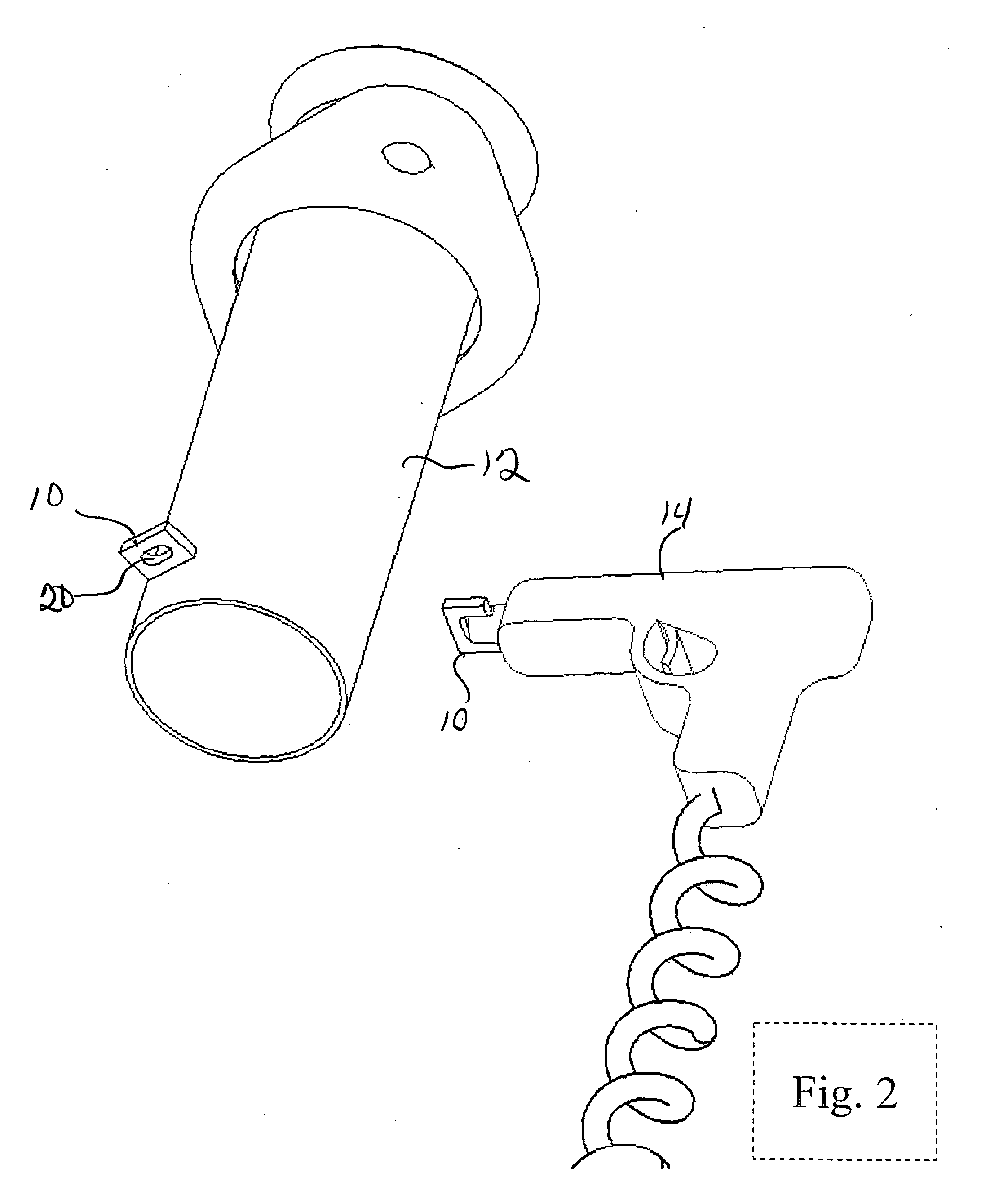
[0023] The disclosed method may be carried out using several different hardware configurations. All of the various hardware configurations provide a mechanical coupling between adjacent portions of a composite tubular assembly. The mechanical coupling in its most basic form includes a plurality of axially extending threaded studs joined to one end of a tube and radially extending anchors affixed to an end of an adjacent tube. The threaded studs and anchors are configured and arranged such that the free ends of each threaded stud passes through an aperture defined by an anchor. A threaded nut is engaged with the studs and tightened to bring the end faces of the tubes into compressive engagement. Before the nuts are fully tightened, the radial and circumferential alignment of the tube ends can be adjusted. All of the hardware configurations facilitate alignment of the tubes by permitting some lateral and rotational movement of one tube relative to the other. The studs and anchors are ...


PUM

PropertyMeasurementUnit
Angleaaaaaaaaaa
Forceaaaaaaaaaa
Angleaaaaaaaaaa

Abstract

The present invention discloses a method and hardware apparatus that facilitate temporary mechanical alignment and assembly of discrete straight tube portions and tube bend portions. The temporary mechanical assembly permits a fabricator to “mock-up” the desired non-linear composite tube before any of the tube portions are permanently welded to the other.

Description

BACKGROUND OF THE INVENTION [0001] 1. Field of the Invention [0002] The present invention relates generally to tubular assemblies and more particularly to a method for constructing one of a kind non-linear composite tubular assemblies. [0003] 2. Description of the Related Art [0004] Internal combustion engines produce hot exhaust gases which must be collected and directed away from the internal combustion engine. Such collection is typically carried out by means of an exhaust system. Exhaust systems typically begin with an exhaust manifold secured over the exhaust ports on the internal combustion engine. The exhaust manifold collects and combines exhaust flow from the several exhaust ports into a single exhaust outlet. An exhaust pipe typically connects to the exhaust manifold and directs exhaust gases to a catalytic converter, muffler and ultimately to a tailpipe. The exhaust system components are typically tubular assemblies that are connected in a sealed manner to contain the hot...

Claims


Application Information

Patent Timeline
IPC IPC(8): B23P11/00B21D39/03
CPCB23K9/202B23K37/0533B23K2201/06Y10T29/49826F01N2450/22F16L1/10Y10T29/49963F01N13/1805B23K2101/06
Inventor OPPERMAN, DAVID
Owner OPPERMAN DAVID
Why Eureka
Try Eureka