Fastener tape supply unit of fastener stringer continuous manufacturing apparatus

Inactive Publication Date: 2006-09-07
YKK CORP
View PDF7 Cites 3 Cited by
  • Summary
  • Abstract
  • Description
  • Claims
  • Application Information

AI Technical Summary

Benefits of technology

[0015] Thus, according to the present invention, as described above, the position detecting means is disposed at upper and lower move positions of the dancer roller, and when its detection value reaches an upper limit or a lower limit of the upper and lower move positions or escapes from the upper limit or lower limit, a signal is sent to a drive portion of the feed roller portion through the control portion, thereby controlling a rotation speed of the drive roller. For example, when the dancer roller exceeds its upper limit position, the feeding amount of the fastener tape is increased by raising the rotation speed of the drive roller. When the dancer roller moves below the lower limit position, the feeding amount of the fastener tape is decreased by lowering the rotation speed of the drive roller. As a result, the tape tension between the intermittent feeding portion and the feed roller portion can be always kept constant, particularly when the engaging element is attached in which the fastener tape is stopped, even in the continuous operation for a long time. If it is warranted to hold the tension of the fastener tape at a constant level at the time of attachment of the engaging element in this way, an attachment interval (pitch) of the engaging elements is made uniform, thereby obtaining a high quality fastener stringer.
[0016] As for the detecting means, for example, a limit switch or a photoelectric tube can be used. However, preferably, a rotary encoder is mounted on a proximal end of swing of a swing lever as described above, and a swing range of the dancer roller supported rotatably at a front end of the swing lever is detected by the rotary encoder and its detection signal is sent to the control portion. Consequently, mechanical motion can be securely converted to an electric signal, so that durability of the apparatus is improved and transmission of signals becomes extremely accurate, thereby improving reliability in detection accuracy and further control accuracy.

Problems solved by technology

However, when engaging elements are attached to the fastener tape in succession, the engaging elements cannot be attached to the fastener tape at an equal pitch even if the fastener tape is fed intermittently at an equal pitch.
By the way, a fastener tape supplied continuously at a time of manufacturing of the fastener stringer is extremely long, and the tape supply unit often operates continuously for a long time, for example, several hours to several dozen hours at a time.
Moreover, its physical property is likely to change due to influences of humidity and temperature.
Thus, a thickness of the core thread is added to that of the fastener tape itself at a portion having the core thread attached, thereby causing a delicate change in feeding speed of the fastener tape by the feed roller portion and the intermittent feeding portion.
Further, a feeding amount of the fastener tape is changed delicately by an influence by, for example, slippage at the feed roller portion as well.
Although the change in feeding amount is not so large, this grows to a large change in a tremendously large total length by operation for a long time, so that, for example, tape tension increases gradually during the operation, thereby exceeding the weight of the dancer roller.
Consequently, the fastener tape is deposited there and tension adjustment which is an initial purpose becomes impossible, thereby leading a condition in which stopping the manufacturing is unavoidable.

Method used


Image

  • Fastener tape supply unit of fastener stringer continuous manufacturing apparatus
  • Fastener tape supply unit of fastener stringer continuous manufacturing apparatus
  • Fastener tape supply unit of fastener stringer continuous manufacturing apparatus

Examples


Embodiment Construction

[0021] Hereinafter, a preferred embodiment of the present invention will be described specifically with reference to the accompanying drawings.

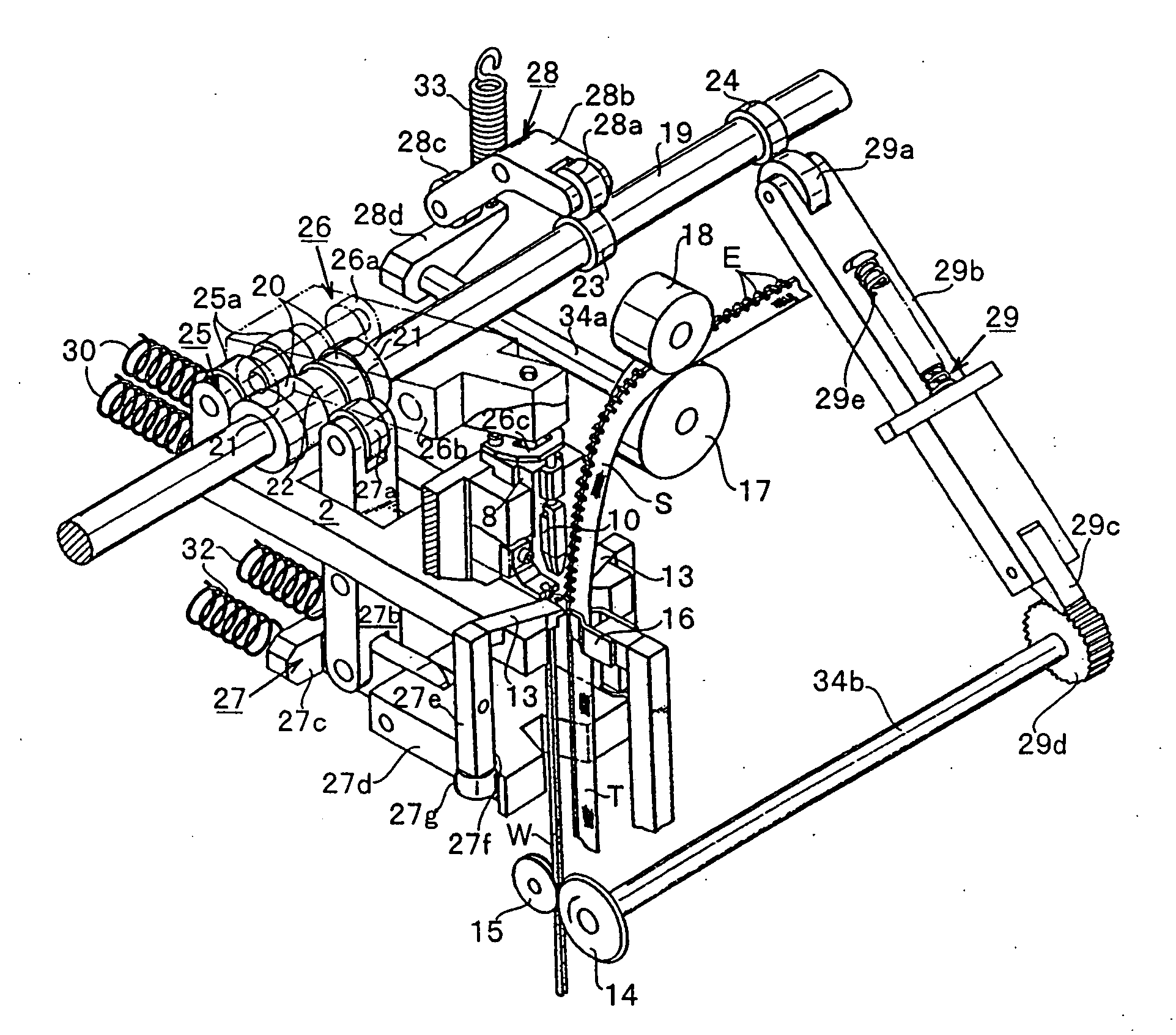
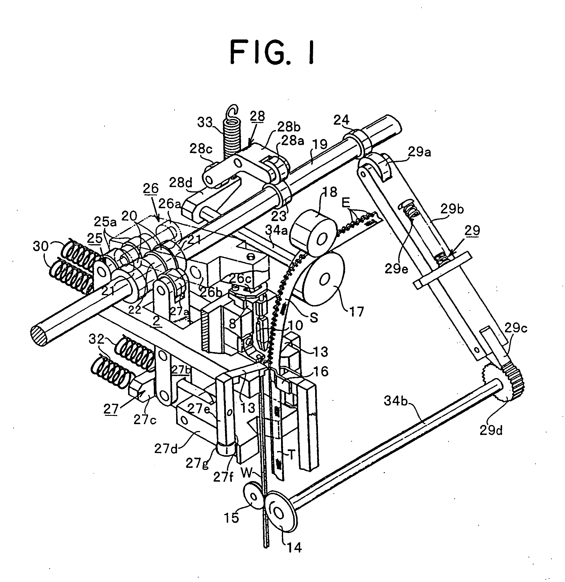
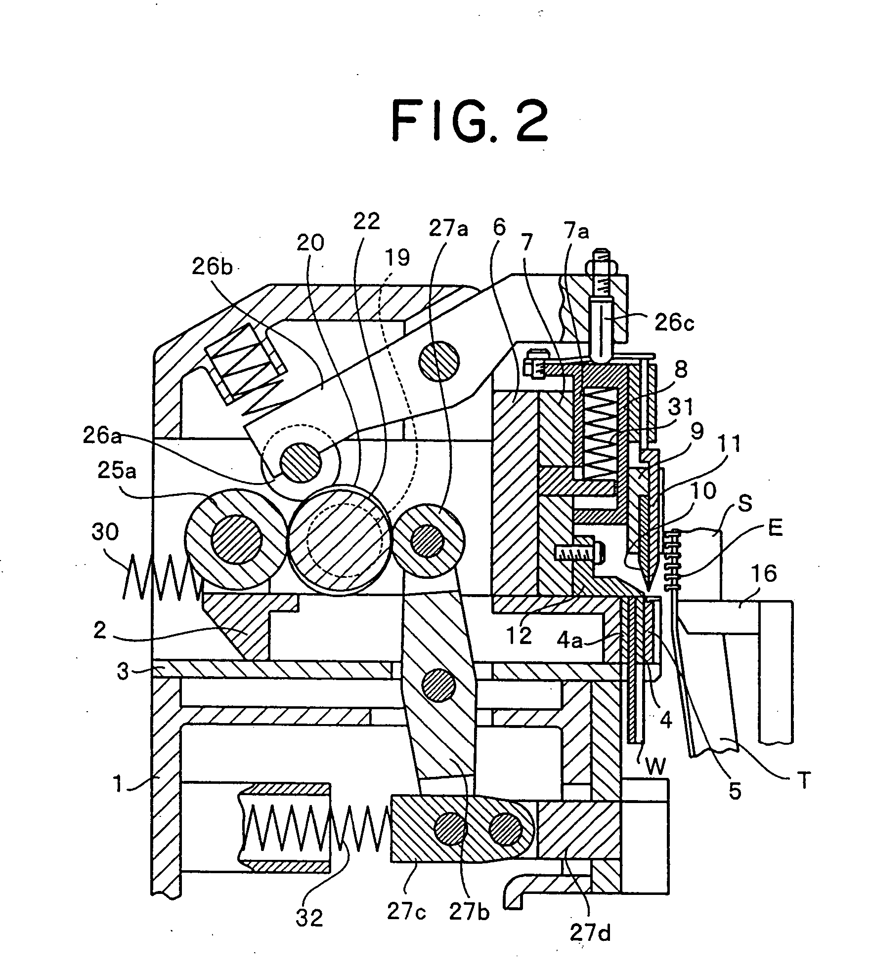
[0022]FIGS. 1 and 2 schematically show an example of major portions of an engaging element forming apparatus for a slide fastener, to which a fastener tape supply unit of the present invention is applied. An indicated structure of the apparatus is not substantially different from the apparatus disclosed in Japanese Patent Publication No. 59-51813. Thus, a following outline of the apparatus is based on description of the publication. In these figures, a first ram 2 is supported on a base 1 through a ram guide 3 so as to freely reciprocate horizontally, and a cutting die 4 and a forming die 5 are provided on a front portion of the first ram 2 in this order in an advancement direction of the first ram 2. The cutting die 4 has an introduction passage 4a for introducing an engaging element irregular shape linear material W having, for example, a ...


PUM


Abstract

The invention provides a fastener tape supply unit applied to a continuous manufacturing apparatus for a fastener stringer, wherein a dancer roller moving up and down corresponding to changes in tape tension is loaded on a fastener tape carried between a feed roller portion for feeding the fastener tape continuously and positively and an engaging element implantation portion, upper and lower limit positions of the dancer roller are detected by detecting means, and when the dancer roller goes out of a range defined by the upper limit position and the lower limit position, a corresponding detection signal is sent to a control portion, the control portion outputs an instruction signal for always holding the dancer roller between the upper and lower limit positions to a drive portion of a drive roller, thereby controlling a tape feeding amount of the feed roller portion to be always constant.

Description

BACKGROUND OF THE INVENITON [0001] 1. Field of the Invention [0002] The present invention relates to a fastener tape supply unit applicable to a continuous manufacturing apparatus for a fastener stringer for attaching an engaging element for a slide fastener to a fastener tape supplied intermittently, wherein the slide fastener is obtained by cutting, in a direction of its lateral section, an engaging element linear material having a substantially Y-shaped section formed by multi-stage rolling. [0003] 2. Description of the Related Art [0004] For this kind of engaging element for slide fastener, a long metallic linear material having a circular section is formed into a substantially Y shape in its lateral section through a plurality of mill rolls, and sequentially cut into a predetermined thickness with a cutting punch and a cutting die to obtain individual engaging element materials. Then, its engaging element head is formed into a mountain-like shape with a forming punch and a form...

Claims


Application Information

Patent Timeline
IPC IPC(8): B32B37/00
CPCA44B19/46Y10T29/5101Y10T156/1712Y10T29/53304B60J1/20B60J3/005E06B9/52E06B2009/527
Inventor TERASAWA, AKINOBUNISHIDA, KAZUYOSHI
Owner YKK CORP
Why Eureka
Try Eureka