High performance defrosters for transparent panels

a transparent panel and high-performance technology, applied in the field of conductive heater grid design, can solve the problems of increasing overall design and shape complexity, limited heat conductivity of plastics, and limitations of plastic modules, so as to increase the spacing between highly visible grid lines, improve the performance of plastic panels or windows, and improve the effect of grid line spacing

Inactive Publication Date: 2006-09-07
EXATEC LLC
View PDF30 Cites 17 Cited by
  • Summary
  • Abstract
  • Description
  • Claims
  • Application Information

AI Technical Summary

Benefits of technology

[0009] The present invention provides a heater grid design for plastic panels or windows capable of defrosting greater than or equal to 75% of the viewing area in a manner that emulates the performance of a conventional heater grid on a glass panel. The present invention allows the spacing between highly visible grid lines to be greater than the conventional spacing of 25-30 mm currently used for heater grids on glass windows. Due to superior performance on a plastic panel or window, the heater grid of the present invention can also be used to increase the grid line spacing for a heater grid on a glass panel or window.
[0011] In another embodiment, the present invention provides a window assembly comprising a transparent panel, a conductive heater grid, and at least one protective coating. The conductive heater grid is formed integrally with the transparent panel having a first group of grid lines and a second group of grid lines, with the width of the grid lines in the second group being less than the width of the grid lines in the first group. The protective coating may further comprise a plurality of protective coatings in a layered structure to enhance protection against weathering and abrasion.

Problems solved by technology

More specifically, plastic materials offer the automotive manufacturer the ability to reduce the complexity of the rear window assembly through the integration of functional components into the molded plastic system, as well as to distinguish their vehicle from a competitor's vehicle by increasing overall design and shape complexity.
Although there are many advantages associated with implementing plastic windows, these plastic modules are not without limitations that represent technical hurdles that must be addressed prior to wide-scale commercial utilization.
Limitations, relating to material properties, include the stability of plastics to prolonged exposure to elevated temperatures and the limited ability of plastics to conduct heat.
Thus a heater grid or defroster designed to work effectively on a glass window may not necessarily be efficient at defrosting or defogging a plastic window.
The low thermal conductivity of the plastic may limit the dissipation of heat from the heater grid lines across the surface of the plastic window.
This difference in conductivity between a heater grid printed on glass and one printed on a plastic window manifests itself in poor defrosting characteristics exhibited by the plastic window as compared to the glass window.

Method used


Image

  • High performance defrosters for transparent panels
  • High performance defrosters for transparent panels
  • High performance defrosters for transparent panels

Examples


example 1

[0066] A heater grid test pattern 18 as shown in FIG. 8 was constructed to evaluate the ability of a various heater grid designs comprising different spacing between the first group of grid lines 20 with width W1 and different numbers of grid lines 35 in the second group with width W2 to defrost a plastic window 16 according to industry standard defrost test protocols and to emulate the defrosting capability of a heater grid on a glass window. A total of 10 different combinations were evaluated in this test pattern. All measurements identifying each combination are provided in Table 3. More specifically, this test pattern evaluated a distance (D1) of 30 mm (a-c), 40 mm (d-f), and 50 mm (g-j) between the first group of grid lines 20, as well as a total of 1 grid line (a), 2 grid lines (b-e, g), 3 grid lines (f and h), 4 grid lines (i), and 5 grid lines (j) within the second group of grid lines 35 between adjacent ones of the grid lines 20 of the first group. The distance between the ...

example 2

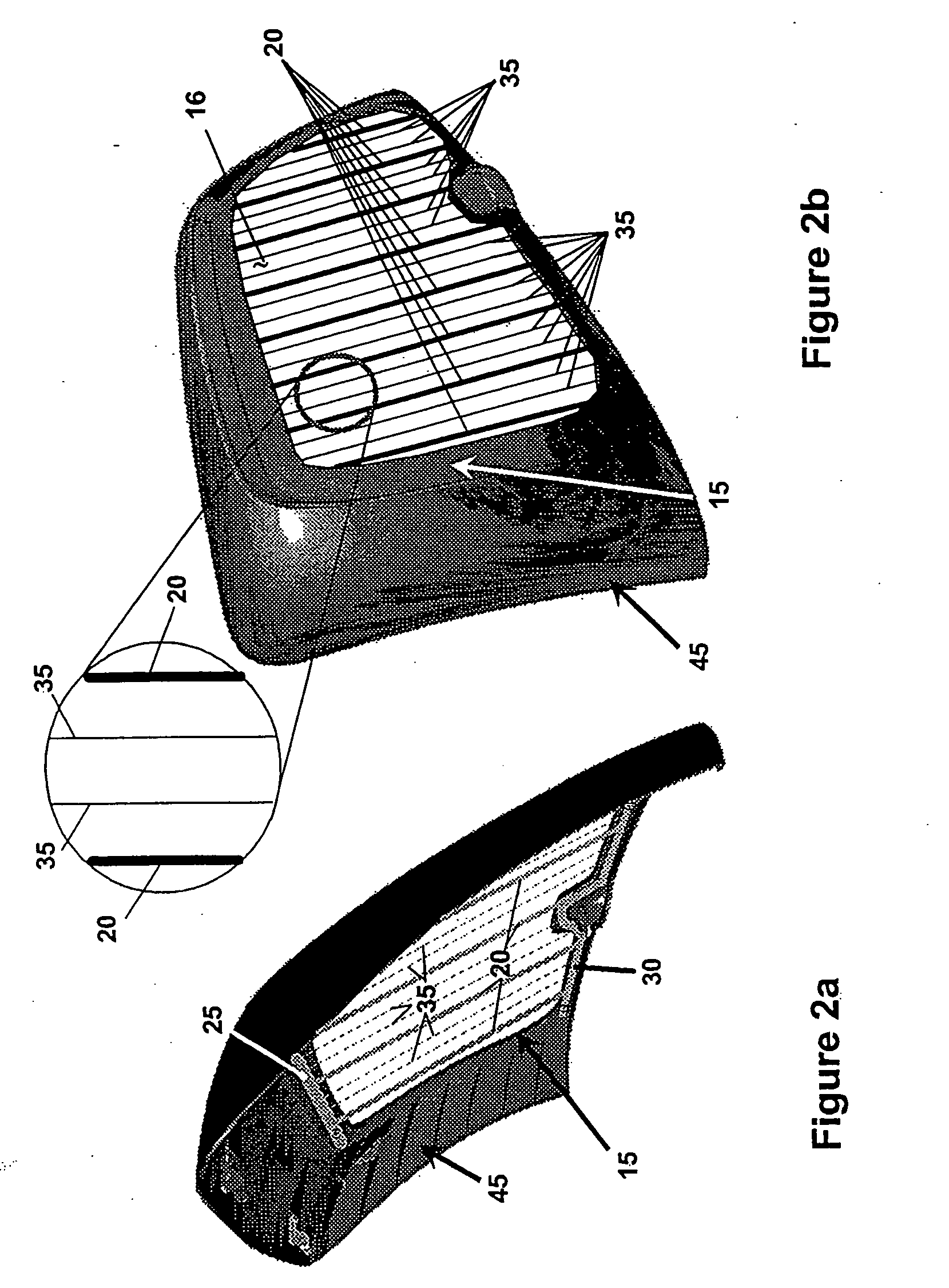
A Heater Grid for a Plastic Automotive Backlight

[0072] A heater grid comprising eight first groups and 8 second groups of grid lines was designed for an automotive backlight as shown in FIG. 3. Each grid line in the first group and second group of grid lines exhibited a width (W1) of 1.25 mm and a width (W2) of 0.225 mm, respectively. Each second group of grid lines was comprised of three grid lines. The length of the gridlines in the first group (L1) and the second group (L2) of grid lines were both about 616 mm. All of the grid lines were relatively parallel to each other with the distance (D1) between the grid lines in the first group being about 50 mm and the distance (D2) between the grid lines in the second group being about 12.5 mm. The resistance of the grid lines in the first group (R1) and in the second group (R2) was 12.5 ohms and 69.5 ohms, respectively. The ratio of (W2 / W1), (D1 / D2), (R2 / R1), and (A2 μl) was determined to be 0.18, 4.0, 5.56, and 0.956, respectively.

[0...


PUM

PropertyMeasurementUnit
resistanceaaaaaaaaaa
temperatureaaaaaaaaaa
velocityaaaaaaaaaa

Abstract

The present invention provides a window assembly having a transparent panel and a conductive heater grid formed integrally with the transparent panel. The conductive heater grid has a first group of grid lines and a second group of grid lines, with opposing ends of each group being connected to first and second busbars. Grid lines of the second group are spaced between adjacent grid lines of the first group, with the height of the grid lines themselves in the second group being less than the height of the grid lines in the first group.

Description

CROSS REFERENCE TO RELATED APPLICATION [0001] This application is a continuation of prior application Ser. No. 10 / 847,250 filed May 17, 2004, the entire contents of which are hereby incorporated by reference.TECHNICAL FIELD [0002] This invention relates to a conductive heater grid design that provides performance within a specific range making it amenable for use in defrosting plastic and glass panels or windows. BRIEF BACKGROUND OF THE INVENTION [0003] Plastic materials, such as polycarbonate (PC) and polymethylmethyacrylate (PMMA), are currently being used in the manufacturing of numerous automotive parts and components, such as B-pillars, headlamps, and sunroofs. Automotive rear window (backlight) systems represent an emerging application for these plastic materials due to many identified advantages in the areas of styling / design, weight savings, and safety / security. More specifically, plastic materials offer the automotive manufacturer the ability to reduce the complexity of the...

Claims


Application Information

Patent Timeline
Patent Type & Authority Applications(United States)
IPC IPC(8): B60L1/02H05B3/84
CPCH05B3/84H05B2203/002
Inventor WEISS, KEITH D.
Owner EXATEC LLC
Why Eureka
Try Eureka