Plant facility

a plant facility and plant technology, applied in the direction of machines/engines, mechanical equipment, electric generator control, etc., can solve the problems of increasing equipment costs, increasing construction time for the facility, and inevitably causing frictional loss between each sliding portion, so as to reduce the frictional loss of bearings, prevent a drop of the availability factor, and eliminate the need for maintenance work

Inactive Publication Date: 2006-09-07
HITACHI LTD
View PDF3 Cites 20 Cited by
  • Summary
  • Abstract
  • Description
  • Claims
  • Application Information

AI Technical Summary

Benefits of technology

[0005] With the above-mentioned related art, however, the provision of the lubricant supply equipment requires a larger equipment installation area as a whole and increases the equipment cost. In addition, the construction time for the facility is also prolonged because of the necessity of installing the lubricant supply equipment and routing the piping. Further, although the lubricant is supplied to lubricate frictional sliding portions of the slide bearings and tooth surfaces of the speed reducer for the purpose of reducing frictional losses, some frictional loss is inevitably caused between each sliding portion and a lubricant film.
[0008] According to the present invention, the lubricant supply equipment for supplying the lubricant to the rotor bearings and the speed reducer can be dispensed with. This leads to various advantages in points of cutting the cost, the installation space and the installation time of the lubricant supply equipment, eliminating the need of maintenance work for lubricant supply lines, reducing frictional losses of the bearings and the speed reducer which are supplied with the lubricant, and preventing a drop of the availability factor caused by troubles in the lubricant supply lines.

Problems solved by technology

With the above-mentioned related art, however, the provision of the lubricant supply equipment requires a larger equipment installation area as a whole and increases the equipment cost.
In addition, the construction time for the facility is also prolonged because of the necessity of installing the lubricant supply equipment and routing the piping.
Further, although the lubricant is supplied to lubricate frictional sliding portions of the slide bearings and tooth surfaces of the speed reducer for the purpose of reducing frictional losses, some frictional loss is inevitably caused between each sliding portion and a lubricant film.

Method used


Image

  • Plant facility
  • Plant facility
  • Plant facility

Examples


first embodiment

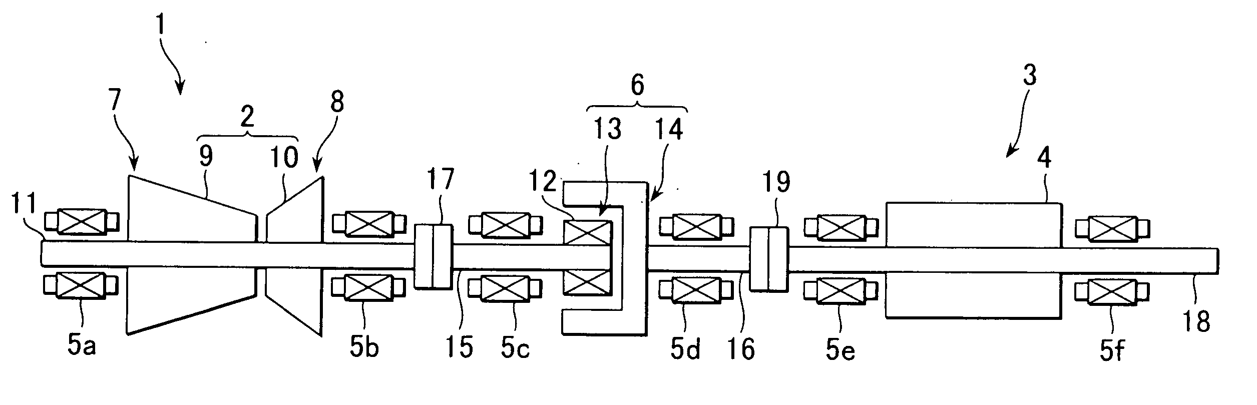
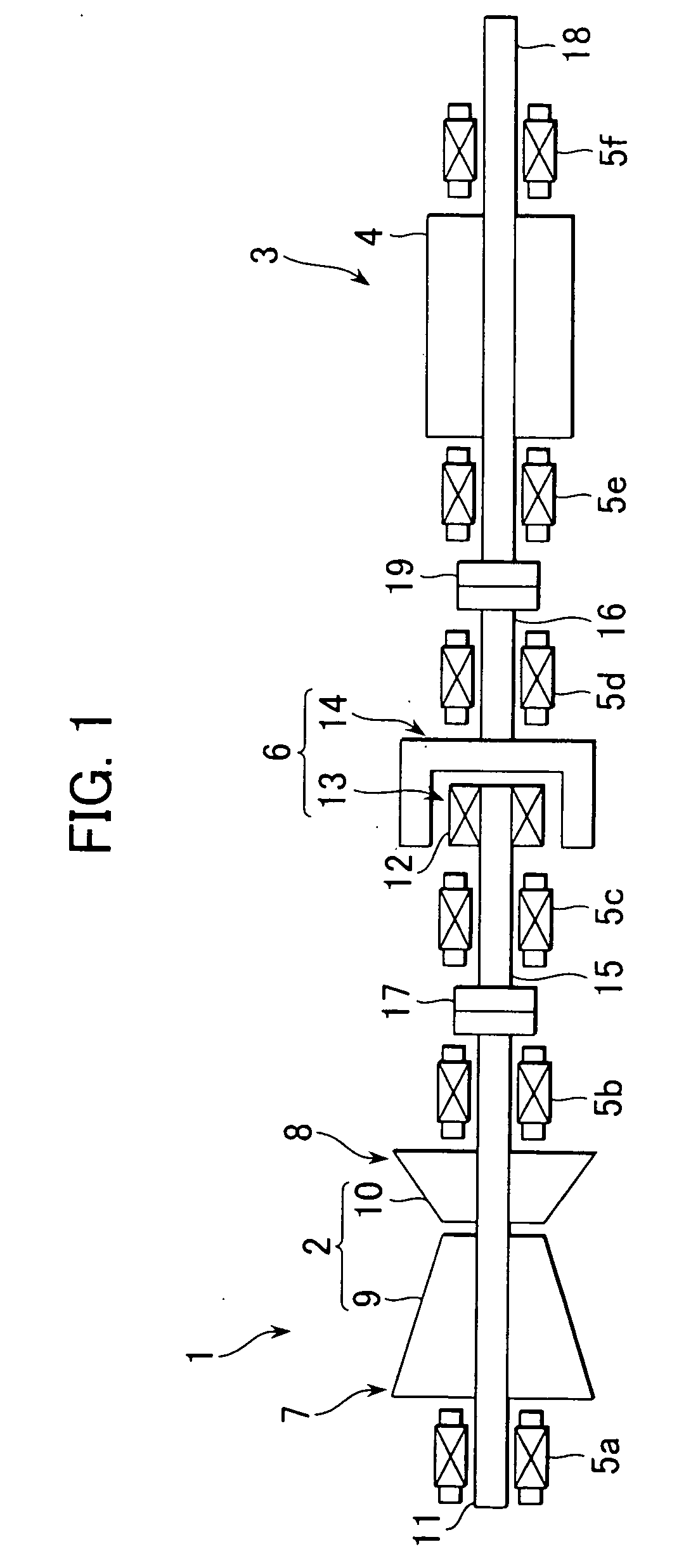
[0015] the present invention will be described below with reference to the drawings.

[0016] Note that, while the following embodiments of the present invention will be described, by way of example, in connection with a power generation facility using a gas turbine, the technical concept of the present invention is also applicable to another type of power generation facility in which a steam turbine, a diesel engine or the like is used as a prime mover and a driving rotor of such a prime mover is connected to a generator rotor for generation of electric power. Further, the present invention is not limited to the case of driving the power generator by the prime mover, but it can be also applied to the case where a pump, a gas compressor, etc. is used as load equipment driven by the prime mover. While the gas turbine is described in each of the following embodiments as a single-shaft gas turbine in which a turbine rotor is not divided, the present invention is similarly applicable to th...

second embodiment

[0040] the present invention will be described below.

[0041] In the second embodiment, a gas turbine and a steam turbine both serving as prime movers are installed one on each of opposite sides of a power generator serving as load equipment such that the power generator is driven by either the gas turbine or the steam turbine. While this embodiment is described, by way of example, in connection with the case where the power generator 3 is arranged between the gas turbine and the steam turbine, the power generator may be arranged between two gas turbines and driven by one of the two gas turbines, or the power generator may be arranged between two steam turbines and driven by one of the two steam turbines. As a matter of course, an engine, e.g., a diesel engine, may be used as one (or both) of the two prime movers. In addition, the load equipment is not limited to the power generator and may be replaced with a pump, a gas compressor, etc.

[0042]FIG. 5 is a schematic view showing the ov...


PUM


Abstract

A plant facility in which lubricant supply equipment for supplying a lubricant to rotor bearings and a speed reducer can be dispensed with. The plant facility comprises a gas turbine rotor of a gas turbine that serves as a prime mover driven by expansion work of a working fluid, a generator rotor of a power generator that serves as load equipment rotated by rotational power transmitted from the gas turbine rotor, a plurality of magnetic bearings for supporting the gas turbine rotor and the generator rotor, and an electromagnetic coupling for magnetically coupling the gas turbine rotor and the generator rotor and adjusting a speed reduction ratio between the gas turbine rotor and the generator rotor in accordance with supplied power.

Description

BACKGROUND OF THE INVENTION [0001] 1. Field of the Invention [0002] The present invention relates to a plant facility in which load equipment, such as a power generator, a pump or a gas compressor, is driven by a prime mover having a driving rotor, such as a turbine or an engine. [0003] 2. Description of the Related Art [0004] In a power generation facility, for example, rotational power of a turbine rotor, i.e., a driving rotor provided in a gas turbine or a steam turbine, is generally transmitted to a generator rotor for generation of electric power. In the field of that related art, there is known an example in which a turbine rotor of a gas turbine is connected to a generator rotor through a speed reducer having a predetermined gear ratio (see, e.g., Patent Document 1: JP,A 2003-106171). In such a power generation facility using a turbine, the turbine rotor and the generator rotor each operating as a rotating component are supported by many slide bearings, and a lubricant has to...

Claims


Application Information

Patent Timeline
Patent Type & Authority Applications(United States)
IPC IPC(8): F02B63/04
CPCF01D15/10F02C3/113F02C7/06F02C7/36F16D27/04Y02E20/16F05D2240/515F05D2260/404F05D2260/4041F16C32/04
Inventor KUROKI, HIDETOSHIMARUSHIMA, SHINYAAKIYAMA, RYO
Owner HITACHI LTD
Why Eureka
Try Eureka