
Method of fabricating non-volatile memory

Active Publication Date: 2006-09-07
POWERCHIP SEMICON MFG CORP
View PDF1 Cites 2 Cited by
  • Summary
  • Abstract
  • Description
  • Claims
  • Application Information

AI Technical Summary

Benefits of technology

[0009] Accordingly, at least one objective of the present invention is to provide a method of fabricating a non-volatile memory that can reduce gate resistance, increase memory cell conductivity and increase device performance and stability.
[0010] At least a second objective of the present invention is to provide a method of fabricating a non-volatile memory that can in crease device performance. Furthermore, the fabricating method can simplify the manufacturing process and reduce the production cost.
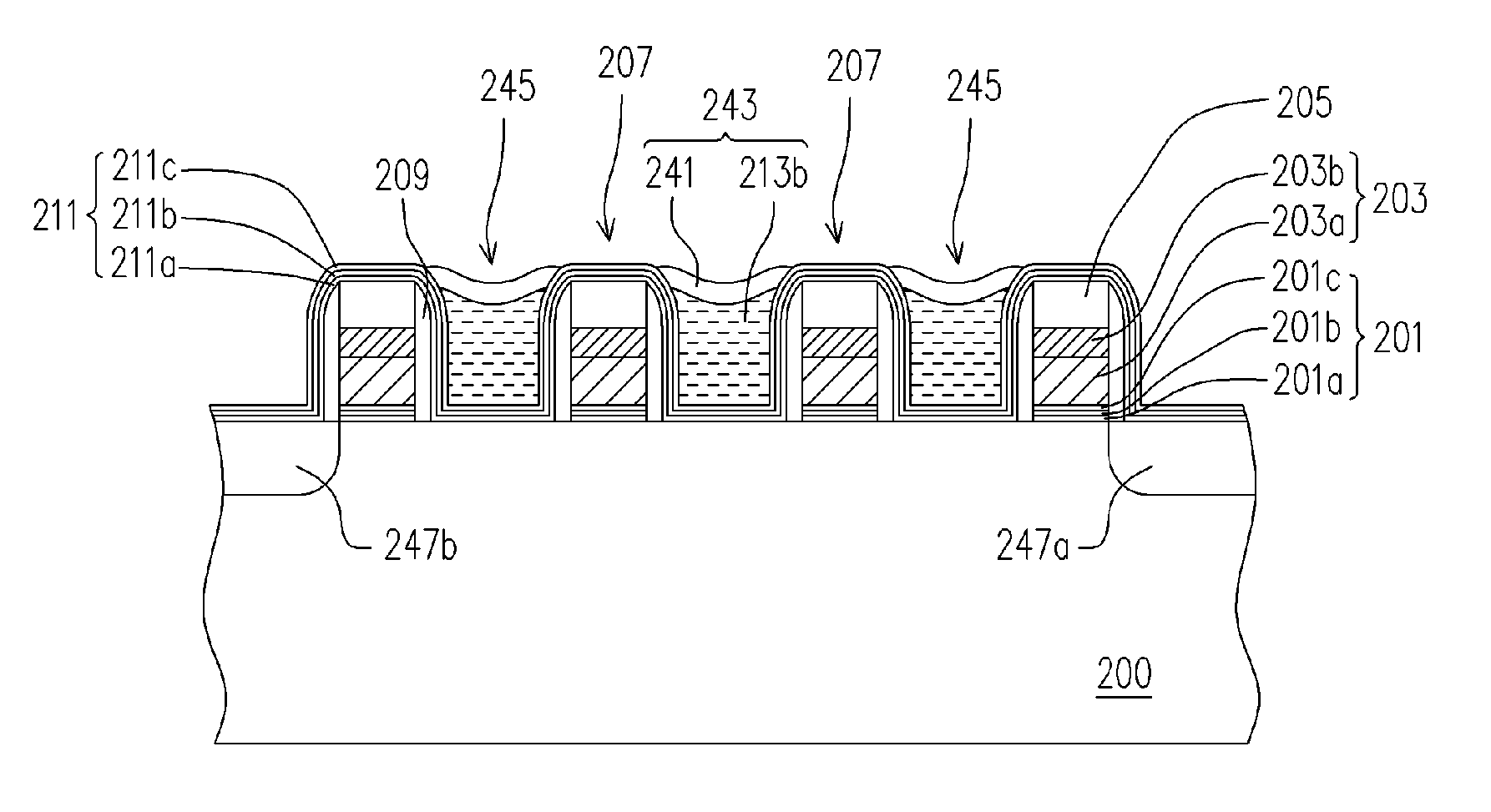
[0021] In the method of fabricating the non-volatile memory according to the present invention, only one photomask is required to define the first memory units and the second memory cells is fabricated without using the conventional photolithographic and etching processes. Therefore, the processing is simplified and the production cost is reduced. Furthermore, using polycide compound to form the gate of the second memory units significantly reduces the gate resistance of the second memory units so that the second memory units can have greater conductivity. The first memory units and the second memory units are electrically comparable. Consequently, the performance and stability of the devices are improved.

Problems solved by technology

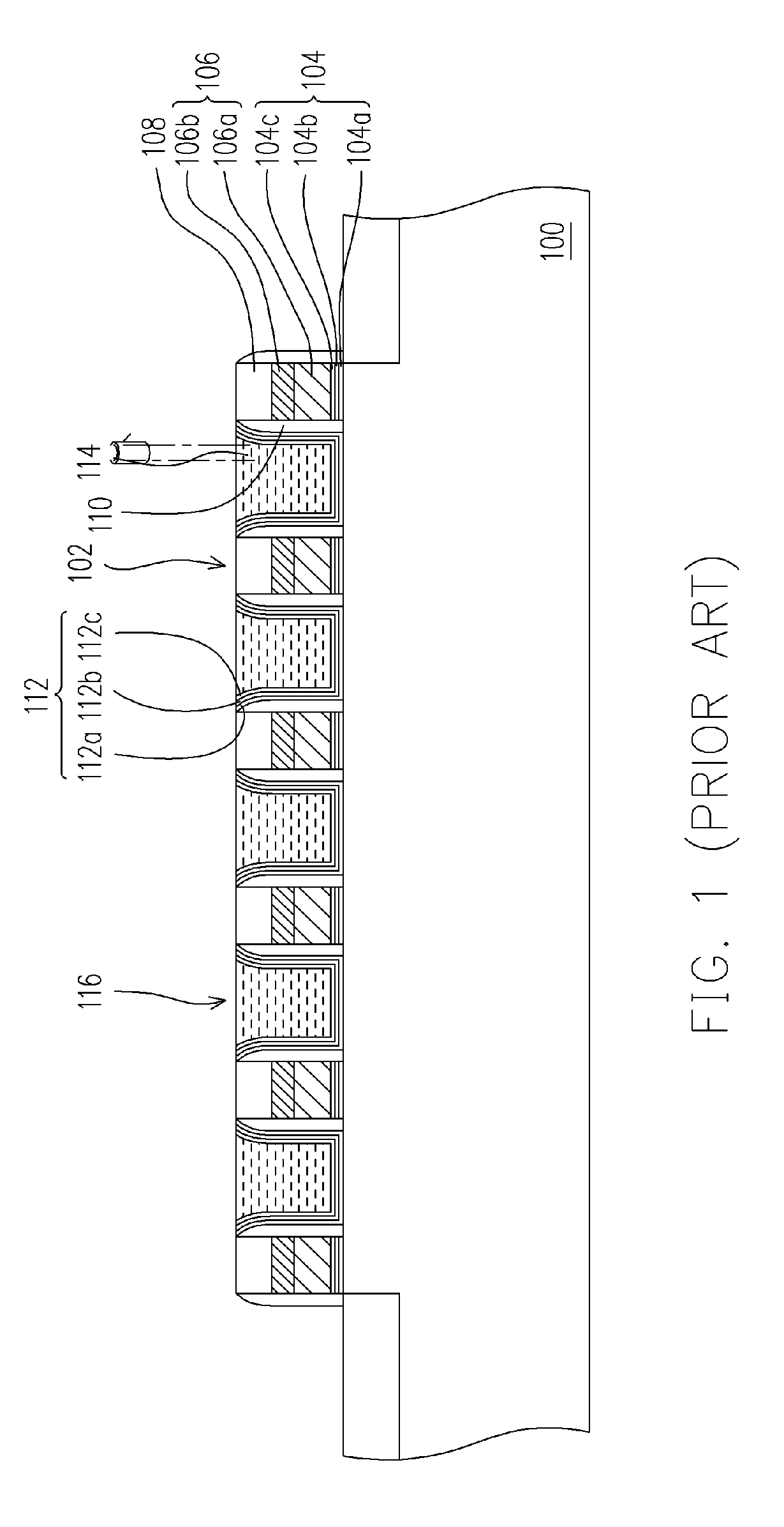
Hence, there will be a drop in the electrical performance of the devices and a greater instability in the device process.

Method used


Image

  • Method of fabricating non-volatile memory
  • Method of fabricating non-volatile memory
  • Method of fabricating non-volatile memory

Examples


Embodiment Construction

[0027] Reference will now be made in detail to the present preferred embodiments of the invention, examples of which are illustrated in the accompanying drawings. Wherever possible, the same reference numbers are used in the drawings and the description to refer to the same or like parts.

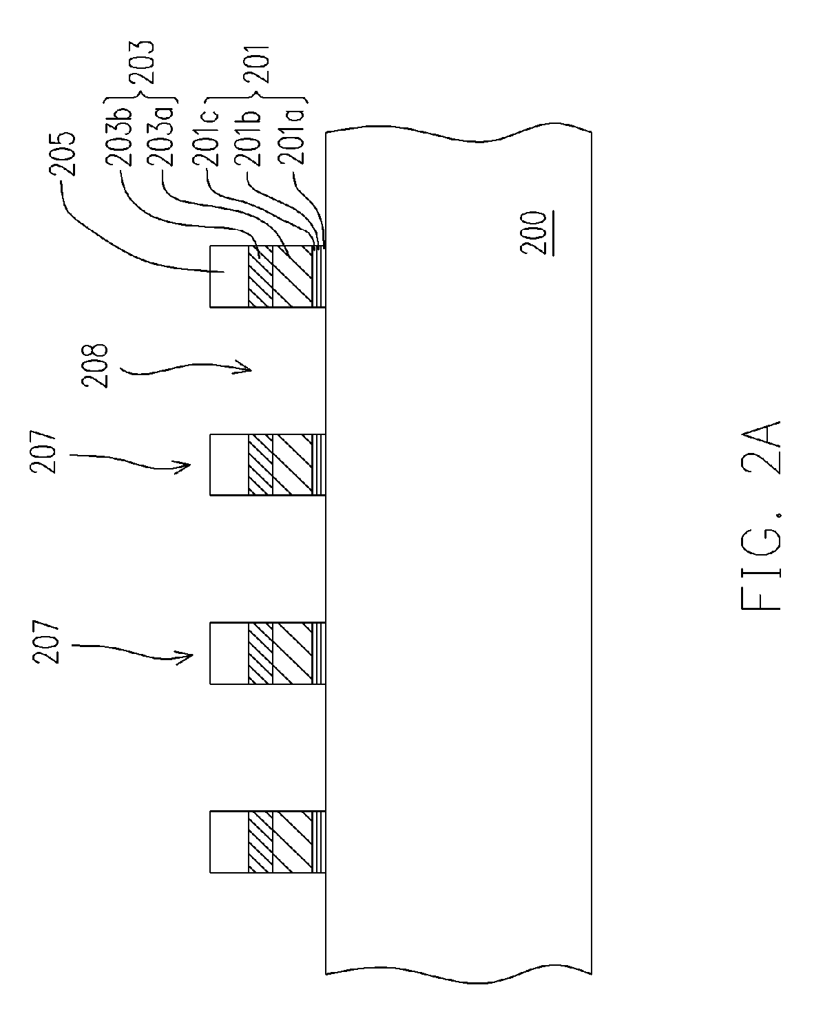
[0028]FIGS. 2A through 2G are schematic cross-sectional views showing the steps for fabricating a non-volatile memory according to one preferred embodiment of the present invention. As shown in FIG. 2A, a substrate 200 is provided. Then, a plurality of memory units 207 is formed on the substrate 200 with every two adjoining first memory units 207 are separated from each other by a gap 208. Each memory unit 207 includes a composite layer 201, a gate 203 and a cap layer 205, for example. The method of forming the memory units 207 includes forming a composite dielectric material layer, a gate material layer and an insulating material layer sequentially over the substrate 100 and patterning the aforeme...


PUM


Abstract

A method of fabricating a non-volatile memory is described. A plurality of first memory units having gaps between each other is formed over a substrate. Insulating spacers are formed on the sidewalls of the first memory units. A composite layer is formed on the substrate and the gaps between the first memory units are filled with a doped polysilicon layer. Thereafter, a portion of the doped polysilicon layer is removed to form trenches. After that, a metallic layer fills the trenches. A portion of the metallic layer is removed to form a plurality of gates. The gates and the composite layer together form a plurality of second memory units. The second memory units and the first memory units together constitute a memory cell column. Then, a source region and a drain region are formed in the substrate adjacent to the two sides of the memory cell column.

Description

CROSS-REFERENCE TO RELATED APPLICATION [0001] This application claims the priority benefit of Taiwan application serial no. 94106211, filed on Mar. 2, 2005. All disclosure of the Taiwan application is incorporated herein by reference. BACKGROUND OF THE INVENTION [0002] 1. Field of the Invention [0003] The present invention relates to a method of fabricating semiconductor memory device. More particularly, the present invention relates to a method of fabricating non-volatile memory. [0004] 2. Description of the Related Art [0005] Among the various types of non-volatile memory products, electrically erasable programmable read only memory (EEPROM) is a memory device that has been widely used inside personal computer systems and electronic equipment. In the EEPROM, data can be stored, read out or erased numerous times and stored data are retained even after power is cut off. [0006] Typically, the floating gate and the control gate of an EEPROM cell are fabricated using doped polysilicon....

Claims


Application Information

Patent Timeline
IPC IPC(8): H01L21/336
CPCH01L27/115H01L27/11568H10B69/00H10B43/30
Inventor CHU, CHIEN-LUNGPITTIKOUN, SAYSAMONEWEI, HOUNG-CHITSENG, WEI-CHUNG
Owner POWERCHIP SEMICON MFG CORP
Learn More