
Wired circuit board

Active Publication Date: 2006-09-07
NITTO DENKO CORP
View PDF12 Cites 24 Cited by
  • Summary
  • Abstract
  • Description
  • Claims
  • Application Information

AI Technical Summary

Benefits of technology

[0009] It is an object of the present invention to provide a wired circuit board that can provide a reduced transmission loss and an improved adhesion strength between a metal suspension board and a metal foil with a simplified laminar structure, thereby providing improved long-term reliability.
[0014] According to the wired circuit board of the present invention, since the thin metal film is formed between the metal suspension board and the metal foil, the transmission loss in the conductive pattern can be reduced and also sufficient adhesion strength between the metal suspension board and the metal foil can be provided with a simple laminar structure wherein only the thin metal film is made to intervene between the metal suspension board and the metal foil, ensuring improved long-term reliability.

Problems solved by technology

This conventional suspension board with circuit exhibits greater transmission loss in the conductive pattern due to the metal suspension board formed of stainless steel.
However, this proposal has the disadvantage that adhesion between the suspension board and the lower conductor is insufficient, so that it is difficult to ensure long-term reliability.

Method used


Image

  • Wired circuit board
  • Wired circuit board
  • Wired circuit board

Examples


example 1

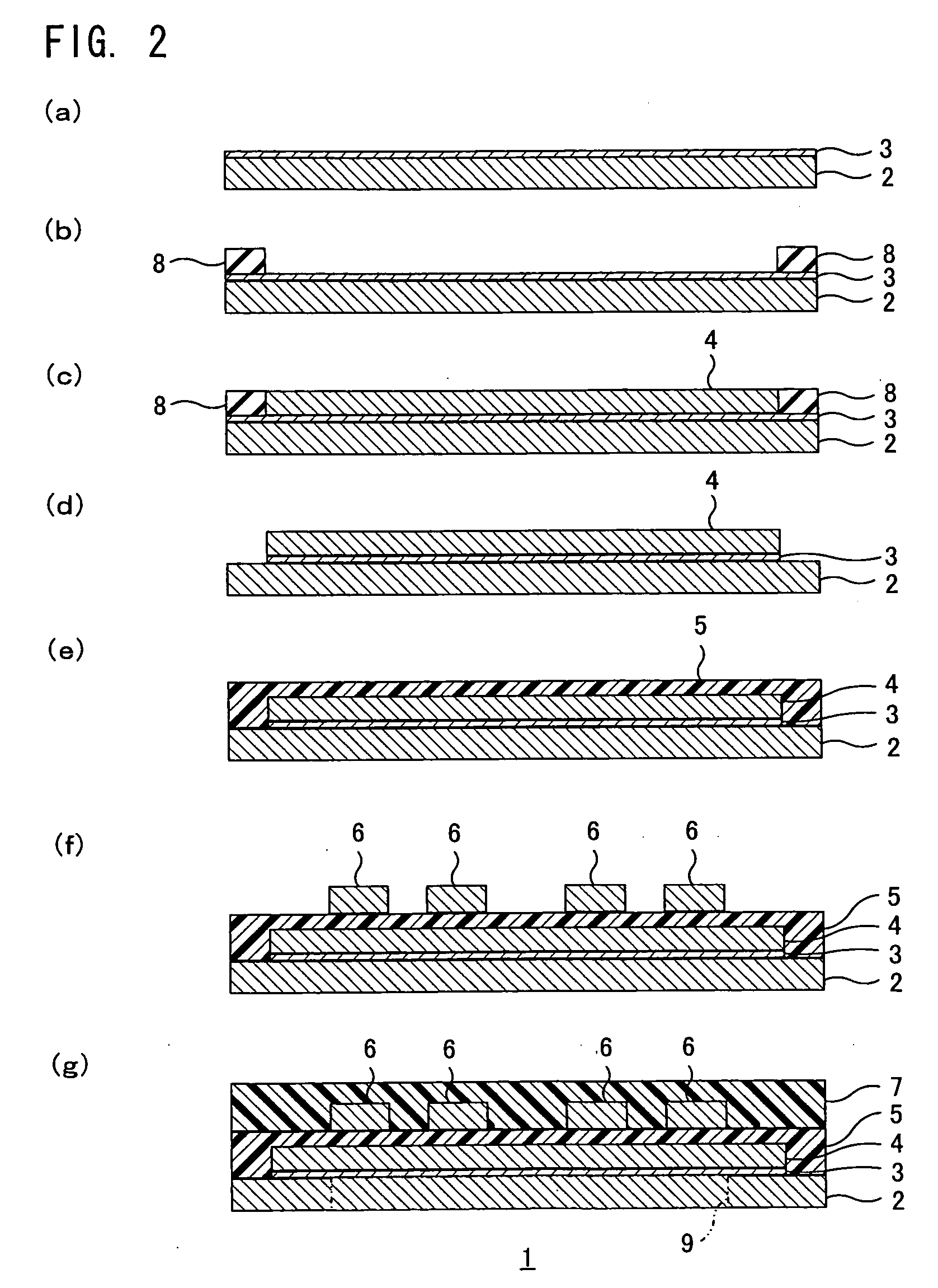
[0050] A thin chromium film of 0.03 μm thick and a thin copper film of 0.07 μm thick, each serving as a thin metal film, were sequentially formed on a metal suspension board of stainless steel of 25 μm thick by sputtering (Cf. FIG. 2(a)). Then, a plating resist of a pattern to be reverse to a pattern of the metal foil was formed on the thin metal film by using a photosensitive dry film resist (Cf. FIG. 2(b)). Then, a copper foil of 4.0 μm thick, serving as the metal foil, was formed on the entire surface of the thin metal film exposed from the plating resist by electrolytic copper plating (Cf. FIG. 2(c)). Then, the plating resist and the thin metal film in an area thereof where the plating resist was formed were removed by a chemical etching (Cf. FIG. 2(d)). Then, after a varnish of a photosensitive polyamic acid resin was coated over the surface of the metal foil and the surface of the metal suspension board, the coating was exposed to light and then developed and further cured by ...

example 2

[0051] Except that a thin nickel-chromium-alloy film of 0.03 μm thick was substituted for the thin metal films used in Example 1, the same operations as those in Example 1 were made to thereby produce a suspension board with circuit.

example 3

[0052] Except that an electrolytic gold plating film (formed by electrolytic gold plating) of 1 μm thick was substituted for the thin metal films used in Example 1, the same operations as those in Example 1 were made to thereby produce a suspension board with circuit.


PUM


Abstract

A wired circuit board that can provide a reduced transmission loss and an improved adhesion strength between a metal suspension board and a metal foil with a simple laminar structure, thereby ensuring improved long-term reliability. The wired circuit board 1 comprises a metal suspension board 2, a thin metal film 3 formed on the metal suspension board 2 by sputtering or by electrolytic plating, a metal foil 4 formed on the thin metal film 3 by electrolytic plating, an insulating base layer 5 formed on the metal foil 4 and the metal suspension board 2, and a conductive pattern 6 formed on the insulating base layer 5 as a wired circuit pattern. The wired circuit board 1 may include an insulating cover layer 7 formed on the insulating base layer 5 to cover the conductive pattern 6.

Description

CROSS REFERENCE TO RELATED APPLICATION [0001] This application claims priority from Japanese Patent Appln. No. 2005-57704, filed Mar. 2, 2005, the contents of which are herein incorporated by reference in their entirety. BACKGROUND OF THE INVENTION [0002] 1. Field of the Invention [0003] The present invention relates to a wired circuit board and, more particularly, to a wired circuit board including, for example, a suspension board with circuit and the like. [0004] 2. Description of the Prior Art [0005] A suspension board with circuit is generally known which comprises an insulating layer formed of resin and a conductive pattern formed of copper which are sequentially formed on a metal suspension board formed of stainless steel. [0006] This conventional suspension board with circuit exhibits greater transmission loss in the conductive pattern due to the metal suspension board formed of stainless steel. [0007] Prior art proposes an attempt solution to reduce the transmission loss, ac...

Claims


Application Information

Patent Timeline
IPC IPC(8): H01R12/00
CPCH05K1/056H05K2201/0317H05K2201/0338H05K2203/0723
Inventor ISHII, JUNKANAGAWA, HITOKIFUNADA, YASUHITO
Owner NITTO DENKO CORP
Features
  • Generate Ideas
  • Intellectual Property
  • Life Sciences
  • Materials
  • Tech Scout
  • Unparalleled Data Quality
  • Higher Quality Content
  • 60% Fewer Hallucinations
Learn More