
Electronic circuit prototyping composite support

a technology of electronic circuit and composite support, which is applied in the direction of programmable/customizable/modifiable circuits, dielectric characteristics, printed element electric connection formation, etc., can solve the problems of no longer re-usable, no longer re-usable, and failure to meet the requirements of the application or removal of the circuit, so as to facilitate the testing of the circuit's operation and feasibility, and the effect of convenient application or removal

Inactive Publication Date: 2006-09-14
CHAN ERIC K D +1
View PDF3 Cites 5 Cited by
  • Summary
  • Abstract
  • Description
  • Claims
  • Application Information

AI Technical Summary

Benefits of technology

[0011] It is another object of the present invention to provide a composite circuit support in which solder may be readily applied or removed by top-soldering operation on the component side of the support.
[0012] It is another object of the present invention to provide an expandable composite circuit support so that the circuit size may be varied selectively as well as providing secure mounting for external devices to the circuit.
[0013] It is yet another object of the present invention is to provide a composite circuit support including a breadboard therein for fabricating a prototype electronic circuit to facilitate testing of its operation and feasibility.
[0014] It is another object of the present invention to provide a method and device for fabricating a prototype electronic circuit without requiring re-construction of a permanent circuit after the prototype has been established.

Problems solved by technology

However, in electronic circuit development it is frequently and inherently required to make numerous changes in various components and / or circuit connections during its testing operation.
Such process is very awkward and troublesome to carry out and it often results in the destruction of the electrical components such that they are no longer re-usable thereafter for other circuit design projects.
Moreover, since the connection eyelets are merely adhered to the board, they would become dislodged from the board by the heat of the soldering iron after several repeated de-soldering and re-soldering operations so that the board may also be no longer re-usable.
Due to the small size of the eyelets, it is very difficult to extract the solder from one side of the eyelet opening when it is necessary to remove a component by de-soldering from underside of the board and it is even more difficult to extract the solder from the inside of the eyelets within the tight space between the component leads and the eyelets.
The process would invariably destroy the components and / or the printed circuit board.
Accordingly, such double sided printed circuit board with small eyelet openings is also not suitable for fabricating prototype electronic circuit.
However, there are numerous drawbacks in using a breadboard.
Firstly, the circuit fabricated on a breadboard is only suitable for temporary testing purposes.
Such re-construction process is time consuming and difficult to carry out as the components lay out and the electrical connections in using a universal printed circuit board usually require complete re-design.
Therefore, it not only would incur additional costs to the user but would invariably introduce other unanticipated complications since the operation and feasibility of such second set of components have not been tested.
In such event, the original breadboard circuit could no longer be preserved for reference in the re-construction of the permanent circuit on the printed circuit board.
Furthermore, a circuit constructed on a breadboard is often very messy particularly with the necessary use of long input / output wiring for connecting to external devices such as motors, switches and displays, etc., which are not mounted securely on the breadboard but are merely located alongside the breadboard.
Thus, it is awkward in moving the circuit constructed on a breadboard from one place to another with all the input / output wires and the unmounted external devices loosely dragging along therewith.
Also, installed jumper wires and components may easily become dislodged or their electrical connections may become loose particularly as the circuit is being moved, resulting in an unreliable circuit.
Moreover, often due to improper insertion of the lead wires into the tie-points, the connection may be loose or short circuited to neighboring tie-points especially when stranded input / output wires are used.
Short circuit between power input wires and other connecting wires is particularly damaging in causing malfunction of the circuit.
Such defect is very difficult to trace and correct.
An attempt to pull the incorrectly inserted connecting wire from the tie-point may result in deforming or destroying the spring socket contact to render it unusable thereafter.

Method used


Image

  • Electronic circuit prototyping composite support
  • Electronic circuit prototyping composite support
  • Electronic circuit prototyping composite support

Examples


Embodiment Construction

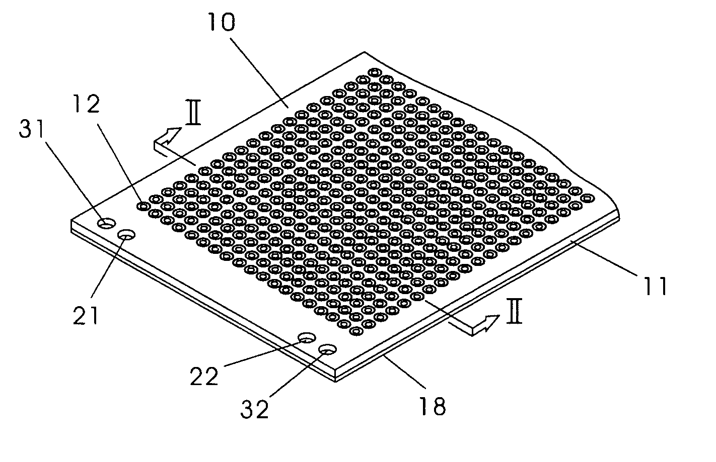
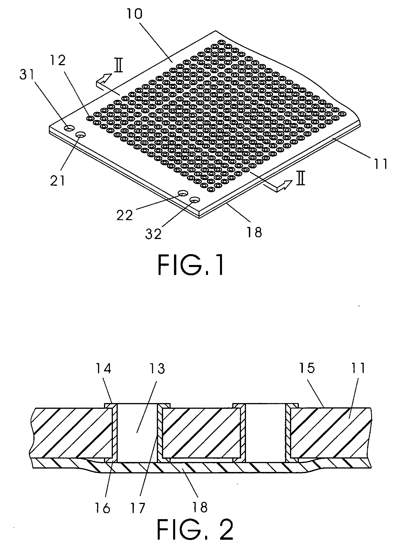
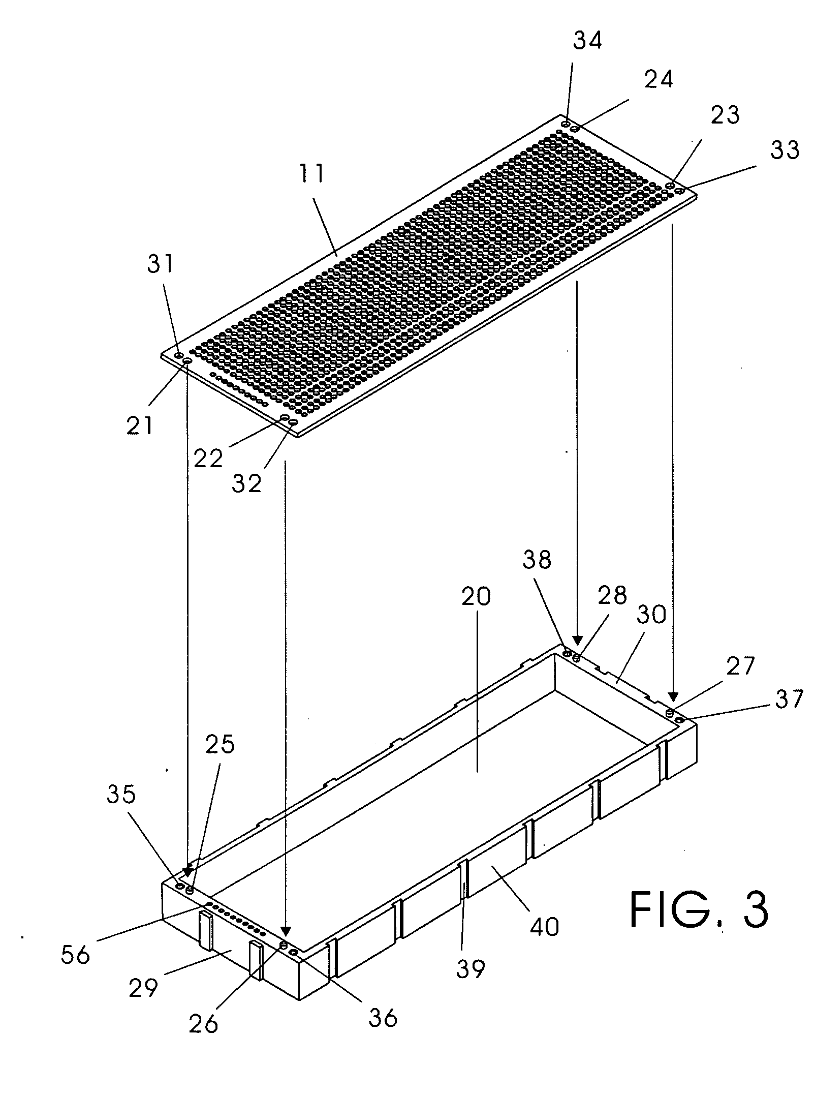
[0036] With reference to the drawings in which like reference numerals in the several views designate corresponding parts, the composite circuit support 10 of the present invention includes a planar board 11 having a plurality of rows and columns of through connection openings 12 formed therein. The planar board 11 is preferably rectangular in shape and is made of a flame-proof plastic or fibreglass material. An annular toroidal connector 13 is located at each through connection opening 12. The annular toroidal connector 13 is made of metal such as copper which has a high affinity to solder, and it has a first annular eyelet 14 located at the top surface 15 of the planar board 11 and a second annular eyelet 16 located directly at the undersurface of the board 11 and directly below the first annular eyelet 14, and a sleeve portion 17 surrounding the inner side wall of the connection opening 12 and extending between and connected to the first eyelet 14 and second eyelet 16 such that t...


PUM

PropertyMeasurementUnit
Lengthaaaaaaaaaa
Lengthaaaaaaaaaa
Lengthaaaaaaaaaa

Abstract

A composite support for fabricating a prototype electrical circuit has a rectangular planar board with a plurality of rows and columns of double sided annular toroidal connection eyelets. The planar board is mounted on a rectangular support tray having a well. The connection eyelets of the planar board have a diameter of from 1.30 mm to 1.80 mm. A high temperature sheet material adhered to the entire undersurface of the planar board, which is pierced by leads of electrical components inserted into the connection eyelets. A spongy retainer block or a breadboard may also be located in the support tray well.

Description

BACKGROUND OF THE INVENTION [0001] 1. Field of the Invention [0002] This invention relates to the method and apparatus for making a prototype of an electronic circuit in circuit development particularly for educational and hobby purposes. [0003] 2. Background Art [0004] In electronic circuit development, following the establishment of the design, it is necessary to build a prototype of the circuit to conduct testing so as to verify its operation and feasibility. The prototype may be built on a universal printed circuit board having an electrical connection pattern provided therein. The pattern consists of a plurality of rows and columns of relatively small openings having a solder connection eyelet commonly made of copper adhered on only its undersurface commonly referred to as the solder side. The openings typically have a diameter of 0.8 mm just sufficient for the leads of electrical components to be inserted therethrough. Leads of electrical components and connection wires are in...

Claims


Application Information

Patent Timeline
IPC IPC(8): H02G3/00
CPCH05K1/0287H05K3/306H05K3/3447H05K3/42H05K13/00H05K2201/0116H05K2201/10401H05K2201/2018H05K2203/0191H05K2203/1189
Inventor CHAN, ERIC K. D.CHU, KING SUM
Owner CHAN ERIC K D
Learn More