

End section of a fluid line with molded-on push-in fitting
- Summary
- Abstract
- Description
- Claims
- Application Information
AI Technical Summary
Benefits of technology
Problems solved by technology
Method used
Image

Examples
Embodiment Construction
OF EMBODIMENTS
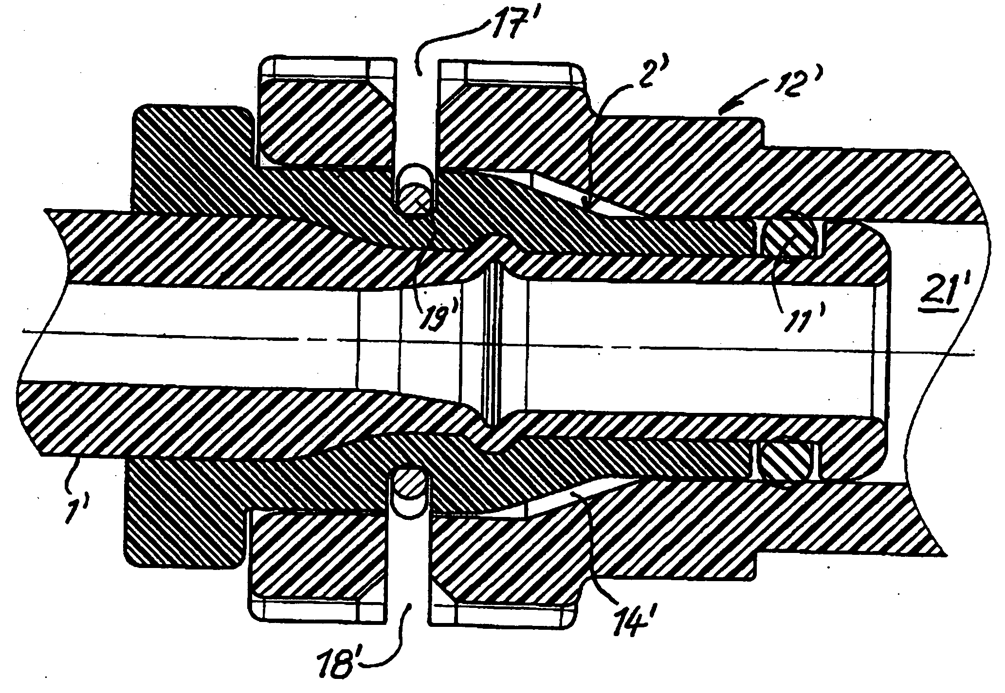
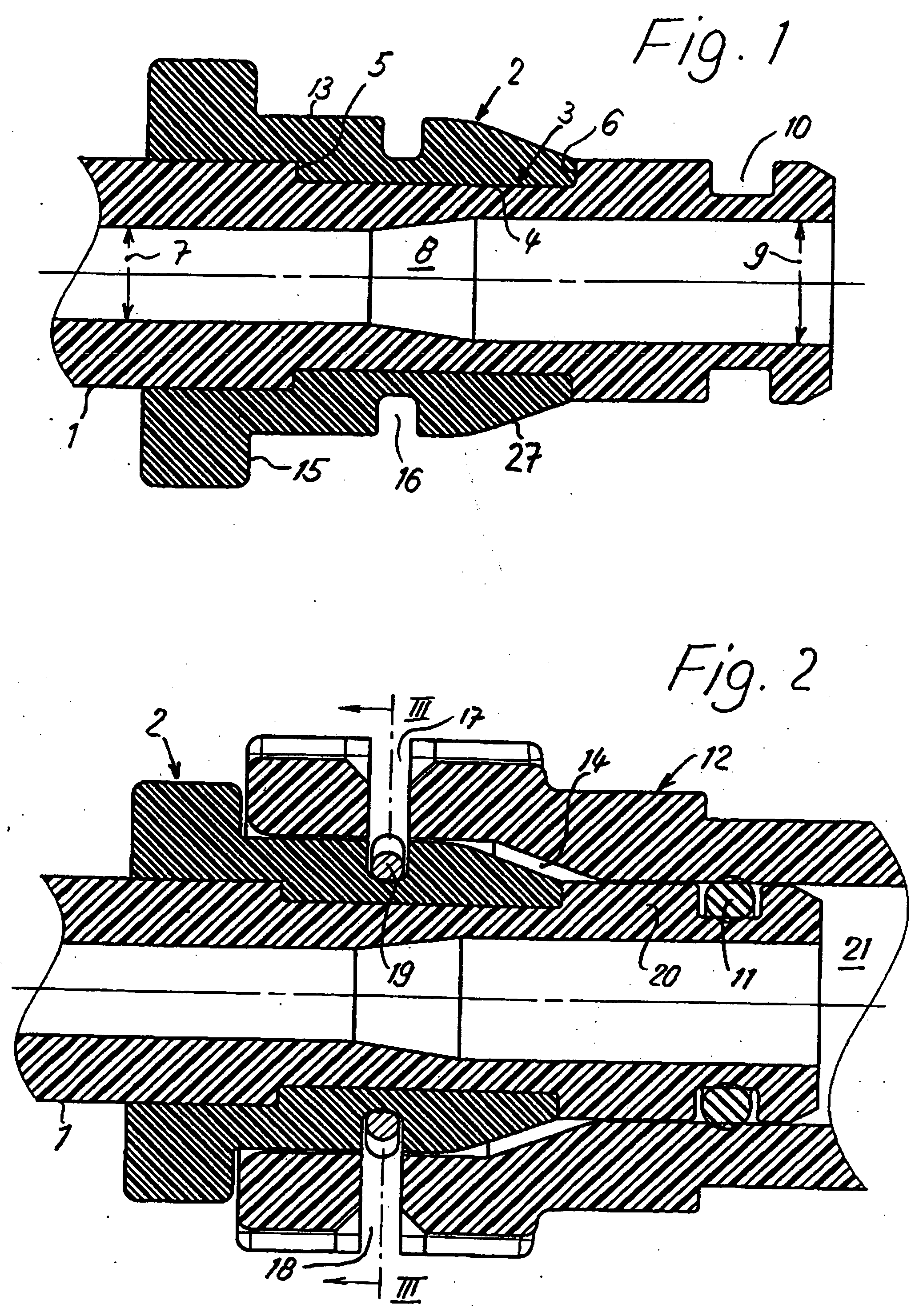
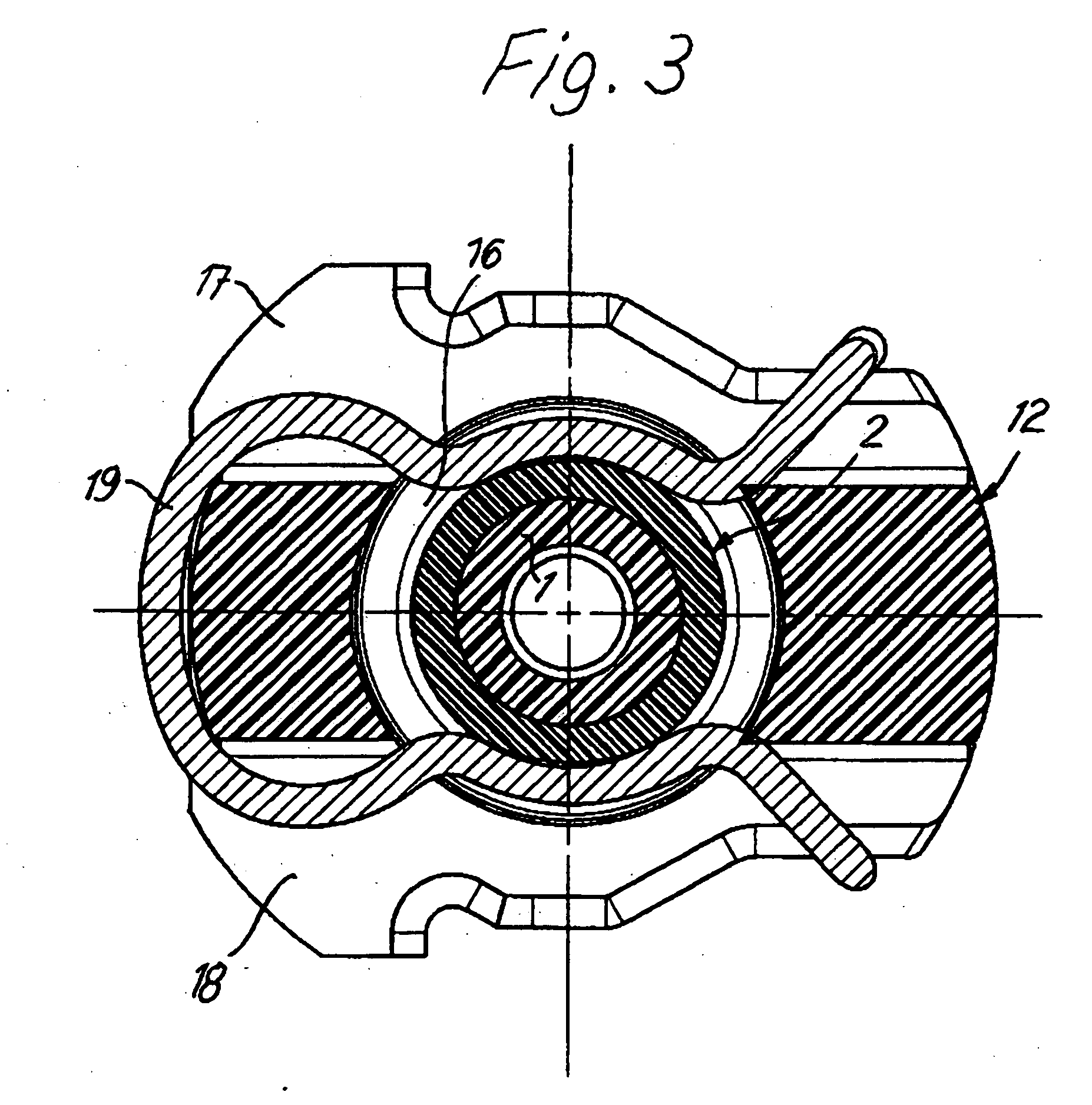
[0029]FIGS. 1 and 2 show the end section of a fluid line 1, which is made of plastic, preferably of polyamide 12. A push-in fitting 2 is molded coaxially onto the end section in the present example of embodiment so as to form a material bond and, as will be described in more detail below, also in a form-fitting manner, by injection-molding a plastic, preferably polyamide 6.6 with a glass fiber content of 35%, around the end section. The two polyamide materials can be adhesion-modified in a known manner in order to improve the binding of the materials.
[0030] Arranged on the end section of the fluid line 1 is a first circumferential groove 3, in the region of which the push-in fitting 2 is molded on with form-fitting penetration of the plastic of the push-in fitting 2 into the first circumferential groove 3. The first circumferential groove 3, which can be formed by machining, has a cylindrical groove bottom 4 coaxial with the longitudinal axis of the end section, and i...
PUM
| Property | Measurement | Unit |
|---|---|---|
| Fraction | aaaaa | aaaaa |
| Force | aaaaa | aaaaa |
| Diameter | aaaaa | aaaaa |
Abstract
Description
Claims
Application Information