Hydrodynamic bearing and method for manufacturing the same, and spindle motor and method for manufacturing the same

a technology of hydrodynamic bearings and spindles, which is applied in the direction of sliding contact bearings, mechanical energy handling, mechanical equipment, etc., can solve the problems of reducing the performance of hydrodynamic bearings, unable to manufacture units in their specified dimensions, and insufficient maintenance of axial axial gaps, etc., and achieves the effect of lowering the performance of spindle motors

Active Publication Date: 2006-09-14
PHC HLDG CORP
View PDF7 Cites 29 Cited by
  • Summary
  • Abstract
  • Description
  • Claims
  • Application Information

AI Technical Summary

Benefits of technology

[0109] During resin coating, extra resin may find its way into the threaded hole and lower the performance of the spindle m...

Problems solved by technology

Nevertheless, a problem is that the welding causes the second flange unit to move in the axial direction, and the heat imparted during welding results in distortion in the form of vertical warping, so the sp...

Method used


Image

  • Hydrodynamic bearing and method for manufacturing the same, and spindle motor and method for manufacturing the same
  • Hydrodynamic bearing and method for manufacturing the same, and spindle motor and method for manufacturing the same
  • Hydrodynamic bearing and method for manufacturing the same, and spindle motor and method for manufacturing the same

Examples


embodiment 1

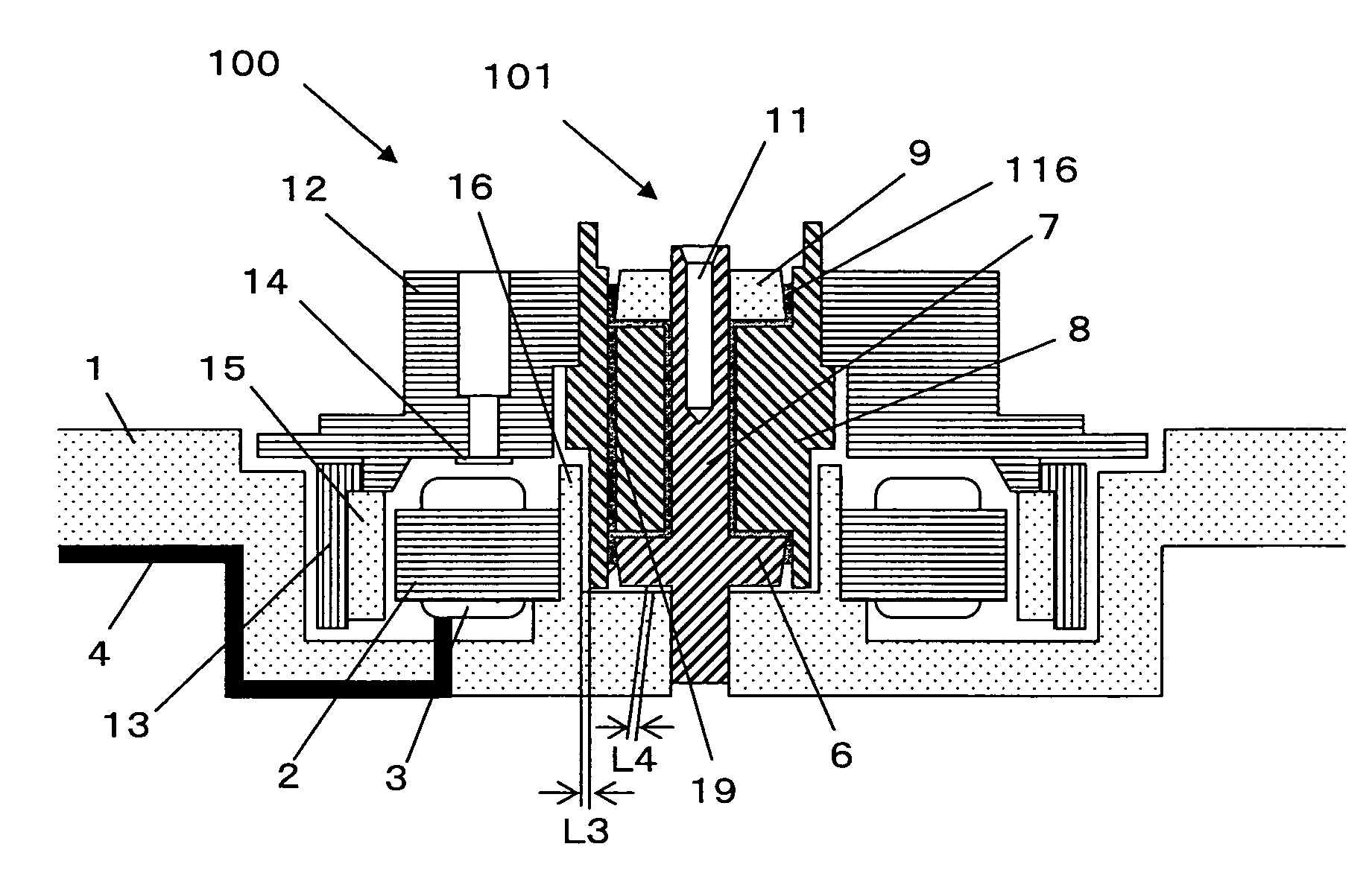
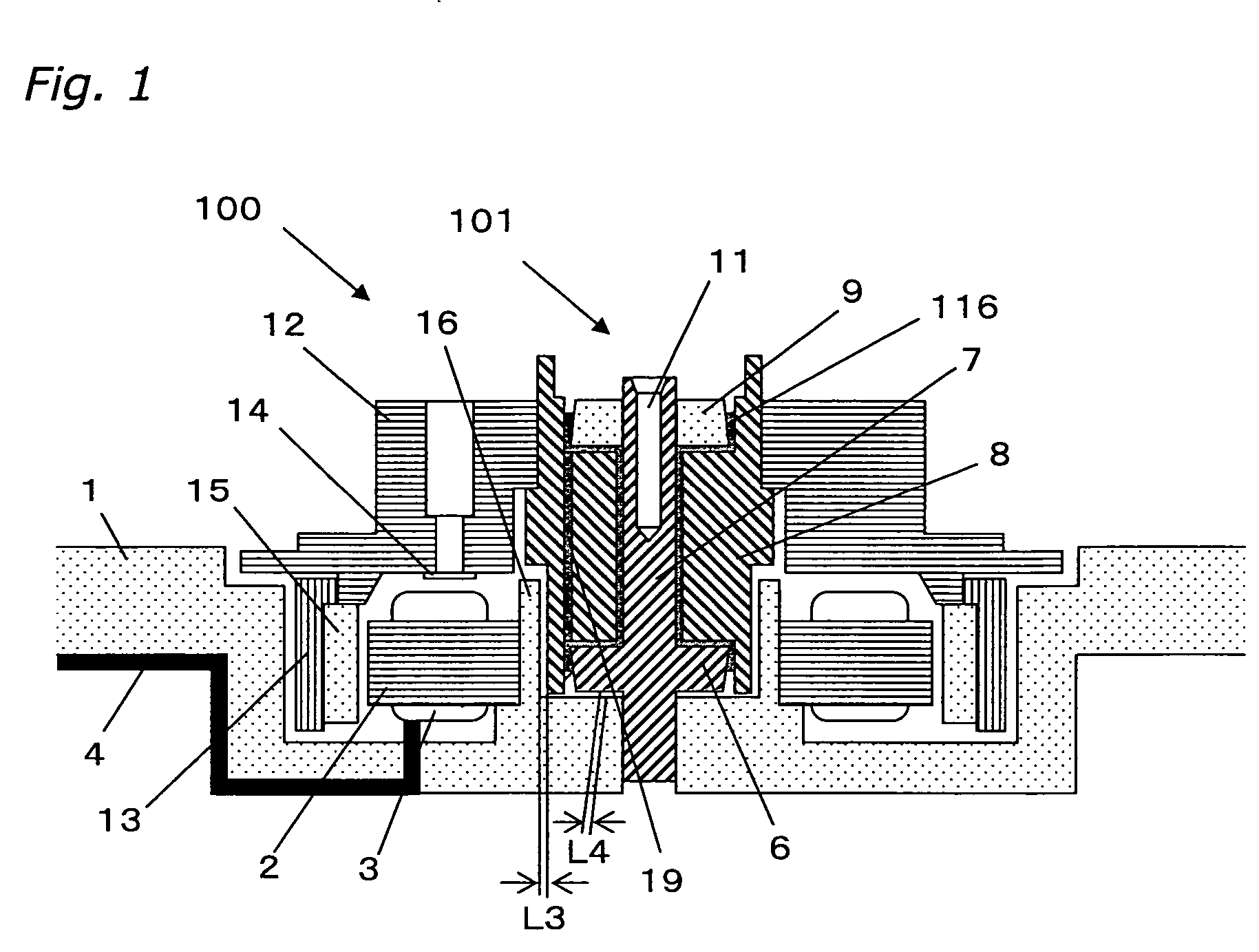
[0134] A spindle motor 100 that features a bearing unit 101 that is the hydrodynamic bearing pertaining to this embodiment will now be described through reference to FIGS. 1 to 5.

Structure of Spindle Motor 100

[0135] In very broad terms, the spindle motor 100 is made up of stationary units and rotating units.

[0136] Examples of the stationary units include, as shown in FIG. 1, a base plate 1, a stator core 2, a coil 3, an insulating tube 4, a first flange unit 6, a shaft 7, a second flange unit 9, and a cylindrical wall 16. The base plate 1 is composed of an aluminum alloy or the like. Silicon steel plate or the like is used for the stator core 2, and the coil 3 composed of a cuprous metal or the like wound around this core to form a stator core assembly. The stator core assembly is fixed to the base plate 1 by press-fitting and adhesive bonding, for example. One end of the insulating tube 4 is inserted to coil leads, and the other end is led out to the outside of the device. A hea...

embodiment 2

[0173] A spindle motor 200 pertaining to this embodiment will be described through reference to FIGS. 10 to 12.

[0174]FIG. 10 is a cross-sectional view of the spindle motor 200.

[0175] In FIG. 10, a housing 51 has a cylindrical unit 51a in its middle, and a sleeve 52 is attached to the cylindrical unit 51a A shaft 53 is rotatably inserted into a bearing hole 52a of the sleeve 52. A flange 55 is attached to the bottom of the shaft 53. An opening at the bottom of the sleeve 52 is sealed off by a thrust receiving plate 54. A fluid such as oil fills the space between the shaft 53 and the sleeve 52 and the space between the thrust receiving plate 54 and the flange 55. This constitutes a hydrodynamic bearing that is known in this field of technology.

[0176] In this embodiment, an aluminum die-cast material or an iron material is used for the housing 51. The sleeve 52 is produced by nickel plating a brass material (copper alloy). A stainless steel material (such as SUS 420J2) is used for t...


PUM

PropertyMeasurementUnit
Shapeaaaaaaaaaa
Distanceaaaaaaaaaa
Elasticityaaaaaaaaaa

Abstract

The object of the present invention is to provide a hydrodynamic bearing, a method for manufacturing the same, and a spindle motor, with which the gap in the axial direction required for the smooth operation of a bearing can be sufficiently ensured. A method for manufacturing a hydrodynamic bearing comprising a shaft 7, a sleeve 8 attached so as to be capable of relative rotation with respect to the shaft 7, a first flange unit 6 fixed to or integrated with the shaft 7, and a second flange unit 9 fixed to the shaft 7, the method comprising at least inserting the shaft 7 into the sleeve 8, and inserting the shaft 7 into the second flange unit 9, pressing the top face of the second flange unit 9 in the axial direction, and fixing the second flange unit 9 to the shaft 7 by welding the shaft 7 and the second flange unit 9 while maintaining the pressing state.

Description

BACKGROUND OF THE INVENTION [0001] 1. Field of the Invention [0002] The present invention relates to a hydrodynamic bearing used in a spindle motor or the like, to a method for manufacturing the bearing, to a spindle motor, and to a method for manufacturing the motor. [0003] 2. Description of the Related Art [0004] The spindle motors installed in disk drives such as hard disk drives (hereinafter referred to as HDDs) have in recent years been hydrodynamic bearing motors, which involve non-contact rotation and therefore afford reductions in noise and NRRO. [0005] As to the structure of these hydrodynamic bearing motors, FIG. 9 shows a conventional hydrodynamic bearing (see Japanese Utility Model Publication No. 2,525,216, for example), which comprises from a shaft 103, a tapered portion 106, a sleeve 112, and a tapered bearing shell 108. The units on the shaft 103 side are fixed by a screw cramp. In this example, the tapered portion 106 is fitted to the shaft 103 having a similar tape...

Claims


Application Information

Patent Timeline
IPC IPC(8): H02K7/00H02K5/16F16C32/06H02K15/14
CPCH02K7/086Y10T29/49636Y10T29/49009H02K15/14F16C17/107F16C43/02
Inventor MAEKAWA, KAZUNORIYOSHIKAWA, YOSEIKAINOH, NAOSHINAKAMURA, JUNICHISHIRAI, AKIHITO
Owner PHC HLDG CORP
Why Eureka
Try Eureka