Natural gas leak mapper

a natural gas and mapper technology, applied in the field of backscatter absorption gas mapping systems, can solve the problems of malfunctioning industrial equipment, difficult visual determination of the presence and extent of natural gas leakage into the environment, and inability to detect the presence of natural gas leakage,

Active Publication Date: 2006-09-14
SANDIA NAT LAB
View PDF57 Cites 110 Cited by
  • Summary
  • Abstract
  • Description
  • Claims
  • Application Information

AI Technical Summary

Benefits of technology

[0035] Reference symbols are used in the Figures to indicate certain components, aspects or features shown therein, with reference symbols common to more than one Figure indicating like components, aspects or features shown therein.

Problems solved by technology

It is thus difficult, and usually impossible, to visually determine the presence and extent of releases of these gases into the environment.
For example, accidental toxic or combustible gas releases can occur from malfunctioning industrial equipment or from accidents involving the transport of bulk hazardous materials.
While the safety of the public would be greatly enhanced in such circumstances by the easy determination of the location, extent, and motion of these gases, there is no device that is capable of providing this information.
Existing detection technology is labor intensive and costly, requiring manually use of instruments that measure at a single point and in close proximity to the leak source.
Typically, the gas industry finds methane leaks using time consuming point measurement devices that are moved about in the vicinity of a suspected leak.
Although BAGI systems are able to provide an image of gas locations in the environment, prior art BAGI systems suffer from limitations that prevent them from being generally useful in producing real-time images of low concentrations of a gas naturally present in the environment.
Problems in making BAGI measurements are generally related to the difficulties in obtaining backscattered light signals of sufficient strength and quality to differentiate localized gas absorption from the background.
Thus, for example, some of the problems include, but are not limited to, variations in the optical properties of backscattering surfaces, scattering of light into collection optics, and detector sensitivity and noise.
In addition, BAGI systems that illuminate a scene also have problems due to, for example, variations in laser power and difficulties in providing sufficient power at useful wavelengths of light.
In addition, since the BAGI image is derived from the total amount of absorbing gas along the system's optical path length, the presence of a background concentration is problematic.
Thus the maximum-light source-to-backscattering surface distance will be limited by the background concentration and resolution of the system.
Another problem with prior art BAGI systems is due to “speckle” that results from reflecting a highly monochromatic light off of the uneven surface.
Thus while the BAGI beams from the light source to the solid surface can have well defined and stable intensity profiles, the return beam has an speckle pattern resulting in intensity variations that introduce noise to the resulting absorption measurement.

Method used


Image

  • Natural gas leak mapper
  • Natural gas leak mapper
  • Natural gas leak mapper

Examples


Embodiment Construction

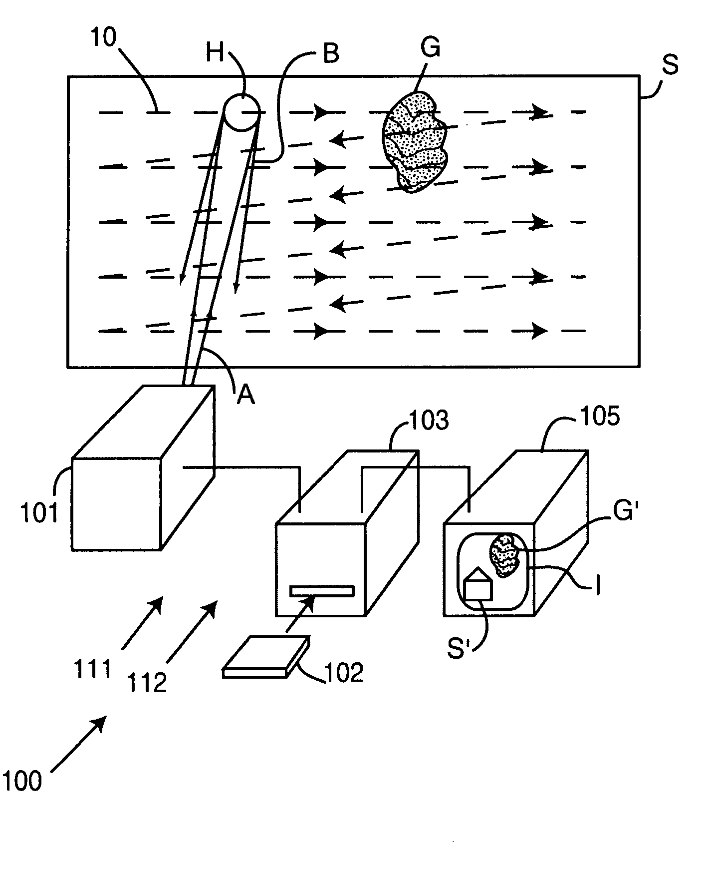
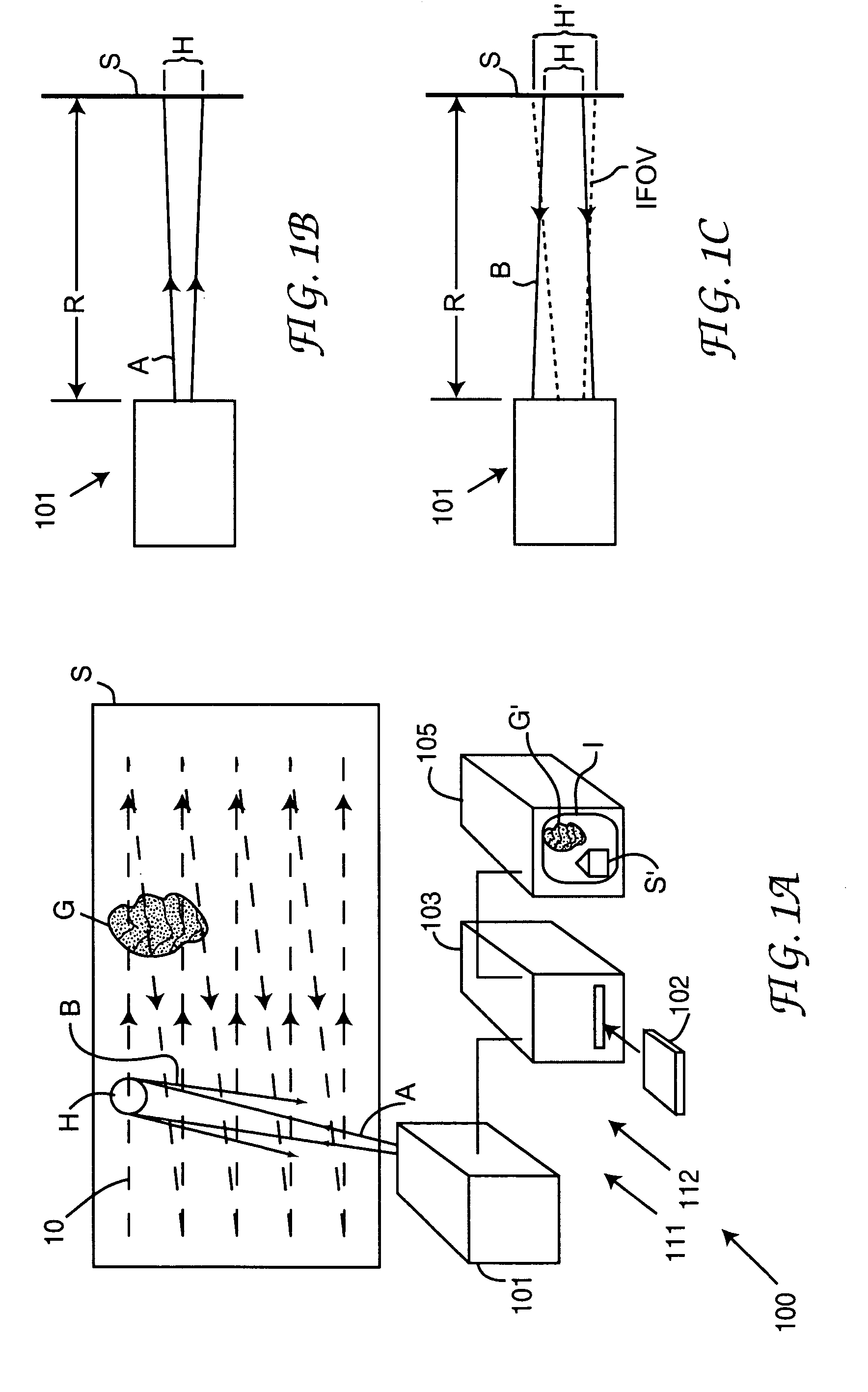
[0036] The present invention will now be described in terms of systems that measure gases of interest by making spectroscopically differentiated absorption measurements of laser light backscattered from a surface in a scene and through the gas. The measurements are described herein as including the use of lasers. The term “laser” as used herein is intended to include lasers as well as any other light sources with spectral and brightness properties meeting the requirements presented in this teaching. For example such light sources could include a laser followed by a frequency conversion device or an incandescent beam from a gas discharge source. The light source is capable of operating in a single-wavelength or differential mode and is designed to produce high-quality images even when the system experiences moderate movement or vibration (such as might occur when the system is driven in a vehicle). In addition, the light or beam generated by the laser is intended to include light at ...


PUM

PropertyMeasurementUnit
frequencyaaaaaaaaaa
widthaaaaaaaaaa
frequencyaaaaaaaaaa

Abstract

A system is described that is suitable for use in determining the location of leaks of gases having a background concentration. The system is a point-wise backscatter absorption gas measurement system that measures absorption and distance to each point of an image. The absorption measurement provides an indication of the total amount of a gas of interest, and the distance provides an estimate of the background concentration of gas. The distance is measured from the time-of-flight of laser pulse that is generated along with the absorption measurement light. The measurements are formated into an image of the presence of gas in excess of the background. Alternatively, an image of the scene is superimosed on the image of the gas to aid in locating leaks. By further modeling excess gas as a plume having a known concentration profile, the present system provides an estimate of the maximum concentration of the gas of interest.

Description

STATEMENT REGARDING FEDERALLY SPONSORED RESEARCH OR DEVELOPMENT [0001] The United States Government has rights in this invention pursuant to Contract No. DE-AC04-94AL85000 between the United States Department of Energy and Sandia Corporation for the operation of Sandia National Laboratories.BACKGROUND OF THE INVENTION [0002] 1. Field of the Invention [0003] The present invention relates to systems to image gases using backscattered absorption gas measurements, and more specifically, it relates to backscatter absorption gas mapping systems for making measurements of gases in the environment. [0004] 2. Discussion of the Background [0005] Most gases are invisible to the unaided human eye, particularly at low concentrations. It is thus difficult, and usually impossible, to visually determine the presence and extent of releases of these gases into the environment. The ability to rapidly detect and track hazardous gases in the atmosphere would greatly aid public safety and health, and wou...

Claims


Application Information

Patent Timeline
Patent Type & Authority Applications(United States)
IPC IPC(8): G01N21/00
CPCG01M3/20G01M3/38G01N21/314G01N21/53
Inventor REICHARDT, THOMAS A.LUONG, AMY KHAIKULP, THOMAS J.DEVDAS, SANJAY
Owner SANDIA NAT LAB
Why Eureka
Try Eureka