
Method for improving the optical polarization properties of a microlithographic projection exposure apparatus

a microlithographic projection and exposure apparatus technology, applied in the field can solve the problem of changing the polarization dependency of the mirror coating, and achieve the effect of improving the optical polarization properties of the microlithographic projection exposure apparatus

Inactive Publication Date: 2006-09-14
CARL ZEISS SMT GMBH
View PDF7 Cites 4 Cited by
  • Summary
  • Abstract
  • Description
  • Claims
  • Application Information

AI Technical Summary

Benefits of technology

[0017] It is therefore an object of the invention to provide a method for improving the optical polarization properties of a microlithographic projection exposure apparatus.
[0021] c) implementing measures which relate to the optical elements identified in step b), in order to improve the optical polarization properties.
[0027] Another measure may consist in extracting the relevant optical element and re-installing it in a different orientation. This is because re-mounting and adjusting the new optical element may lead to forces which cause a lower stress-induced birefringence overall.
[0035] This method of identification according to step b) has the advantage that it is merely necessary to insert comparatively thin polarizers into the beam path, in order to be able to determine at least qualitatively the optical polarization properties of the optical element or elements which lie between the two inserted polarizers.
[0038] The method according to the invention therefore makes it possible to locate optical elements, which intolerably perturb the polarization state, very straightforwardly in the optical system once it has finally been mounted, in order to optionally replace them or implement measures on them which reduce the birefringence. This can obviate time-consuming extraction and installation of all the optical elements, including the necessary adjustment work. This aspect is important, in particular, when an optical system of a microlithographic projection exposure apparatus is intended to be checked in the context of maintenance. The shorter the offline times are in this case, the lower the projection losses during the maintenance work will be.
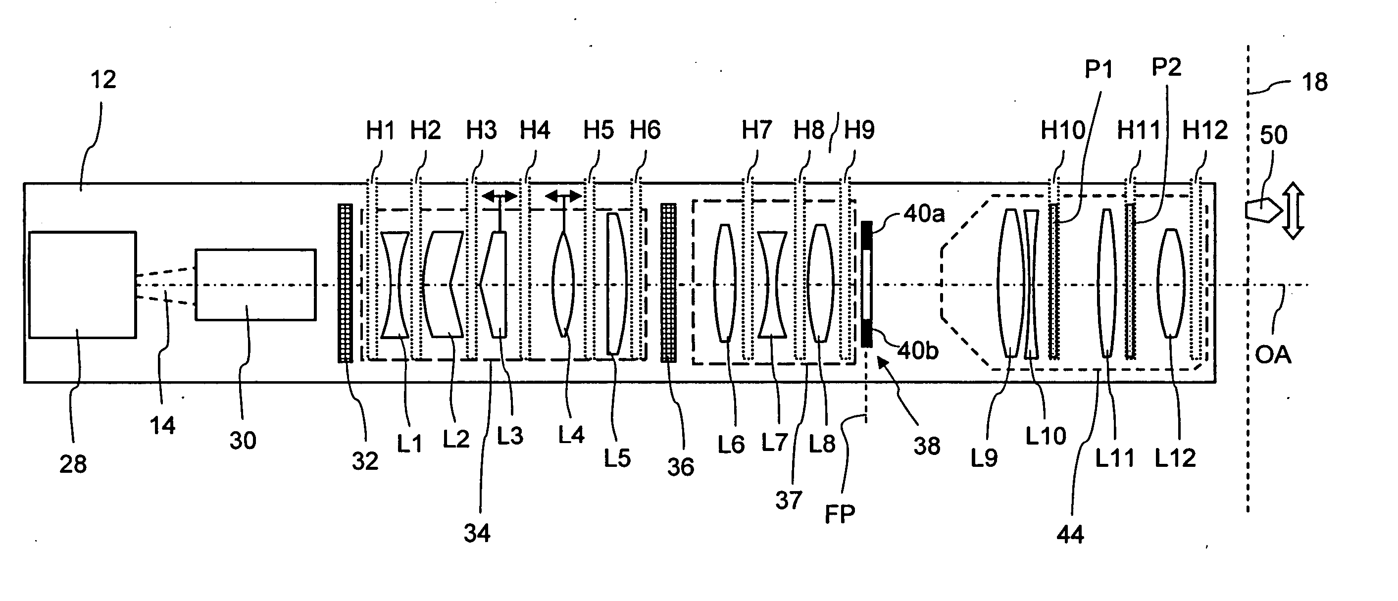
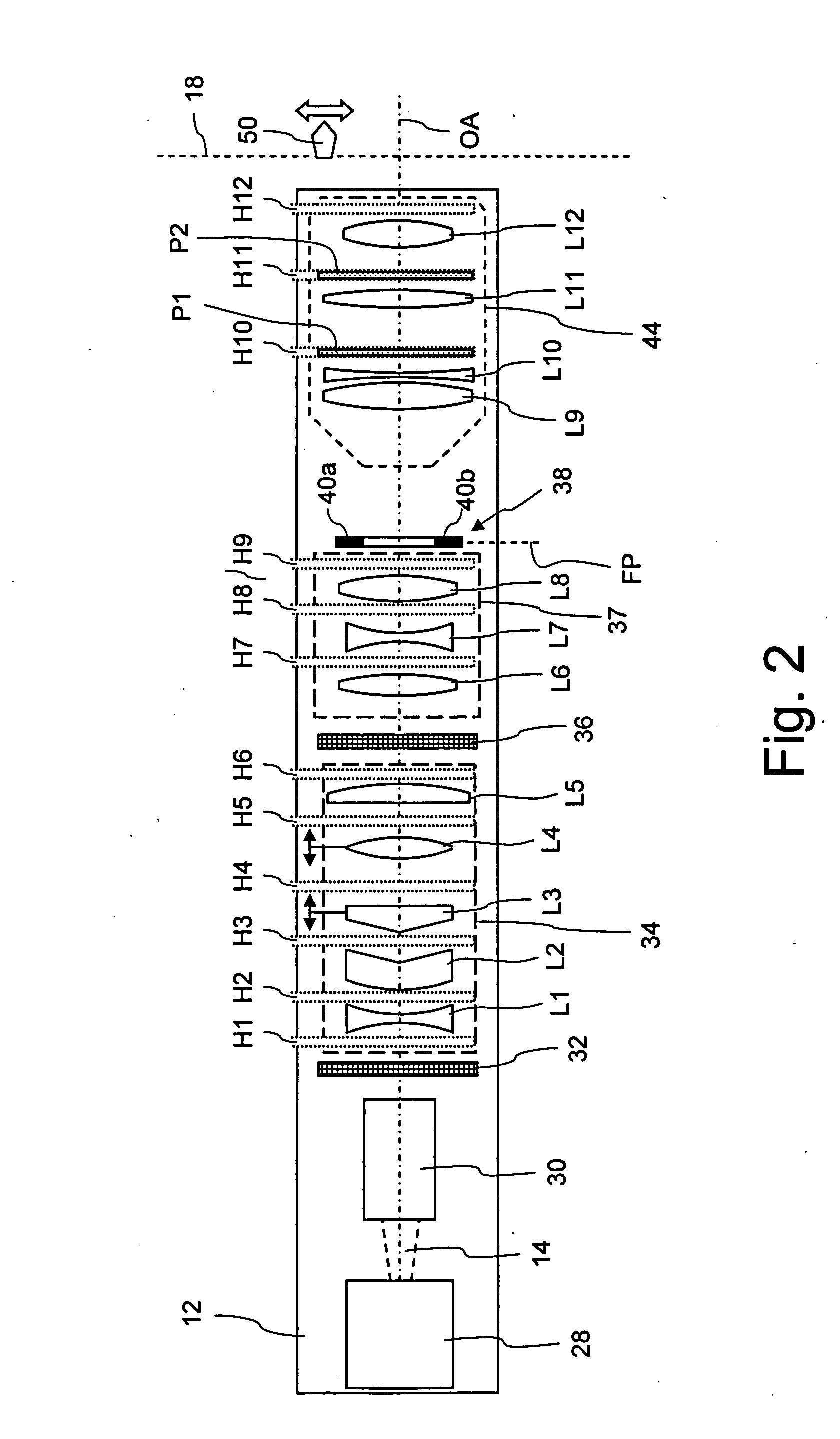
[0039] When more insertion positions are provided in the optical system, the optical elements which intolerably compromise the optical polarization properties can be located with commensurately more accuracy. In the ideal case, there is an insertion position where a polarizer can be inserted immediately in front of and immediately behind each optical element from which significant perturbation of the optical polarization properties may be expected. If the optical system contains N optical elements, for example, then N+1 holders should be provided which need to be arranged between the optical elements so that exactly one optical element is arranged between two holders. In this way, it is possible to analyse each individual optical element at least qualitatively with respect to optical polarization in the finally mounted system.

Problems solved by technology

This is related to the fact that additional forces, the size and direction of which are unpredictable, may be exerted on the lenses during installation of the lens frames in the optical system and subsequent adjustment.
Here again, mounting and adjustment of the mirror holder may lead to material stresses which can slightly change the polarization dependency of the mirror coating.

Method used


Image

  • Method for improving the optical polarization properties of a microlithographic projection exposure apparatus
  • Method for improving the optical polarization properties of a microlithographic projection exposure apparatus
  • Method for improving the optical polarization properties of a microlithographic projection exposure apparatus

Examples


Embodiment Construction

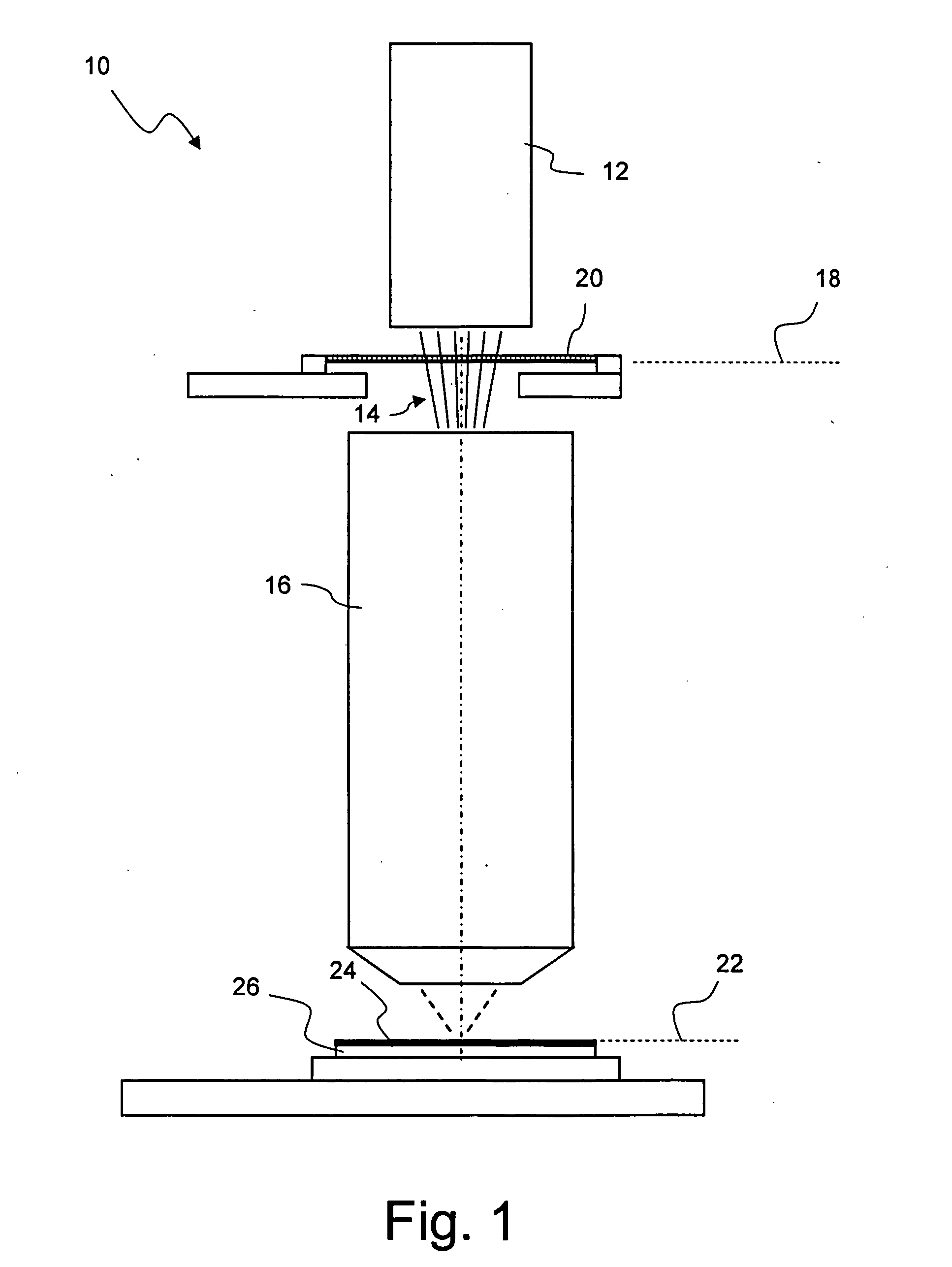
[0056]FIG. 1 shows a projection exposure apparatus, denoted overall by 10, in a simplified side view which is not true to scale. The projection exposure apparatus 10 comprises an illumination system 12, which is used to generate a projection light beam 14, and a projection objective 16, in the object plane 18 of which a mask 20 is arranged in such a way that it can be displaced. In an image plane 22 of the projection objective 16, there is a photosensitive layer 24 which is applied on a substrate 26, which may for example be a silicon wafer.

[0057]FIG. 2 shows details of the illumination system 12 in a schematic representation. The illumination system 12 contains a light source 28 which, in the exemplary embodiment shown here, is an excimer laser generating projection light with a wavelength of λ=193 nm. The projection light beam 14, which initially is still highly collimated, passes through a beam expansion unit 30, a first optical grid element 32, a zoom-axicon objective 34 with o...


PUM


Abstract

An apparatus and method for improving the optical polarisation properties of a microlithographic projection exposure apparatus is disclosed. The method including a first step of providing a mounted optical system of the projection exposure apparatus, which contains a plurality of optical elements; a second step identifying those optical elements that perturb the optical polarisation properties in the mounted optical system to an extent that exceeds a limit value predetermined for the respective optical element; and, a third step implementing measures to improve the optical polarisation properties, which relate to the optical elements identified in the second step.

Description

CROSS-REFERENCE TO RELATED APPLICATIONS [0001] This application claims benefit of provisional application Ser. No. 60 / 637,490 filed Dec. 20, 2004. The full disclosure of this earlier application is incorporated herein by reference.BACKGROUND OF THE INVENTION [0002] 1. Field of the Invention [0003] The invention relates to a method for improving the optical polarization properties of a microlithographic projection exposure apparatus, by which structures contained in a mask can be imaged onto a photosensitive layer. The invention also relates to an optical system of such a microlithographic projection exposure apparatus, which is suitable for carrying out the method. [0004] 2. Description of Related Art [0005] For the production of integrated electrical circuits and other microstructured components, a plurality of structured layers are applied on to a suitable substrate which, for example, may be a silicon wafer. In order to structure the layers, they are first covered with a photores...

Claims


Application Information

Patent Timeline
IPC IPC(8): G02B6/00
CPCG02B27/28G03F7/70258G03F7/70566
Inventor ZENZINGER, MARKUSFIOLKA, DAMIAN
Owner CARL ZEISS SMT GMBH
Learn More