
Molded parts with mixed material surface areas and processes for their production

Inactive Publication Date: 2006-09-14
DOW GLOBAL TECH LLC
View PDF7 Cites 28 Cited by
  • Summary
  • Abstract
  • Description
  • Claims
  • Application Information

AI Technical Summary

Benefits of technology

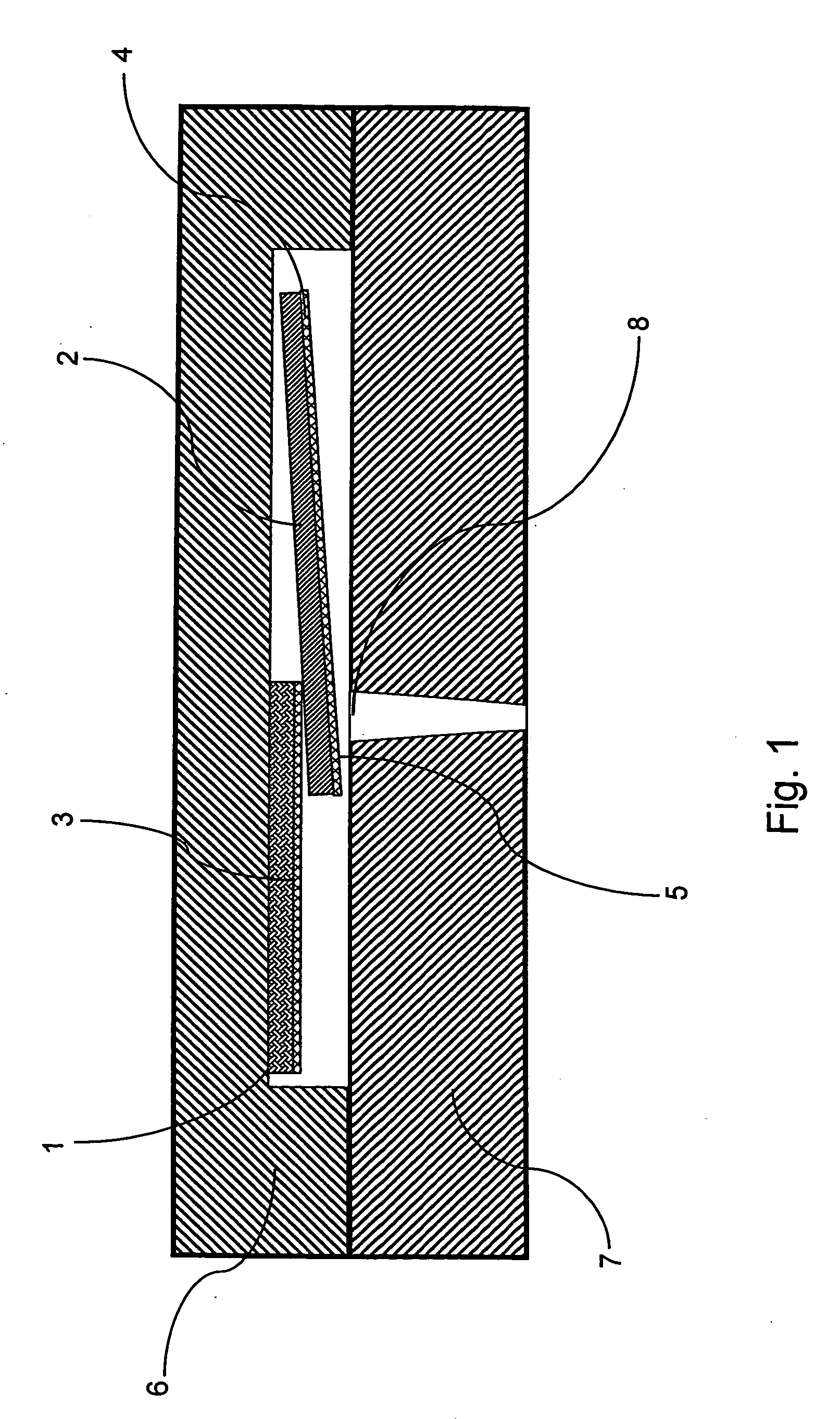
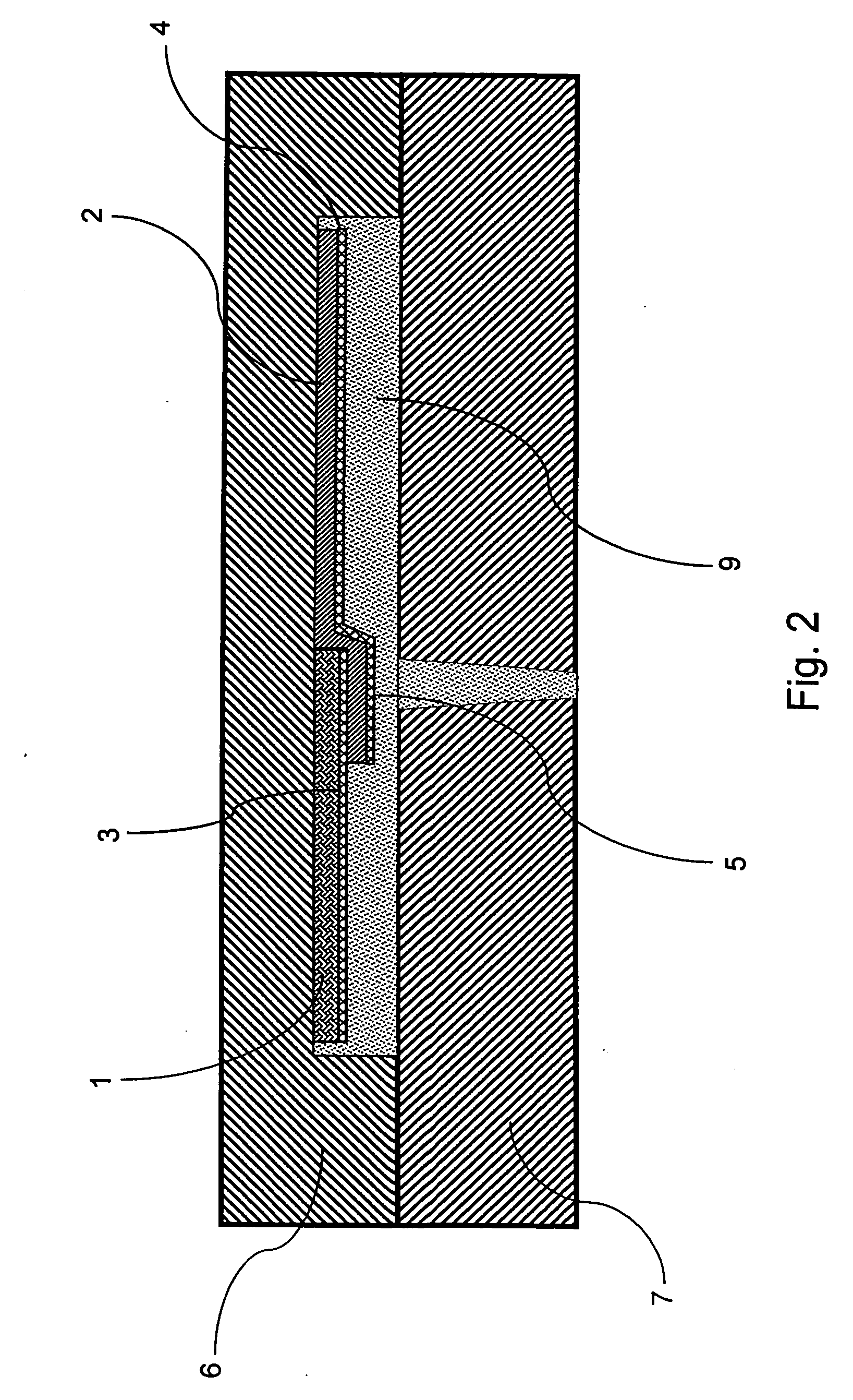
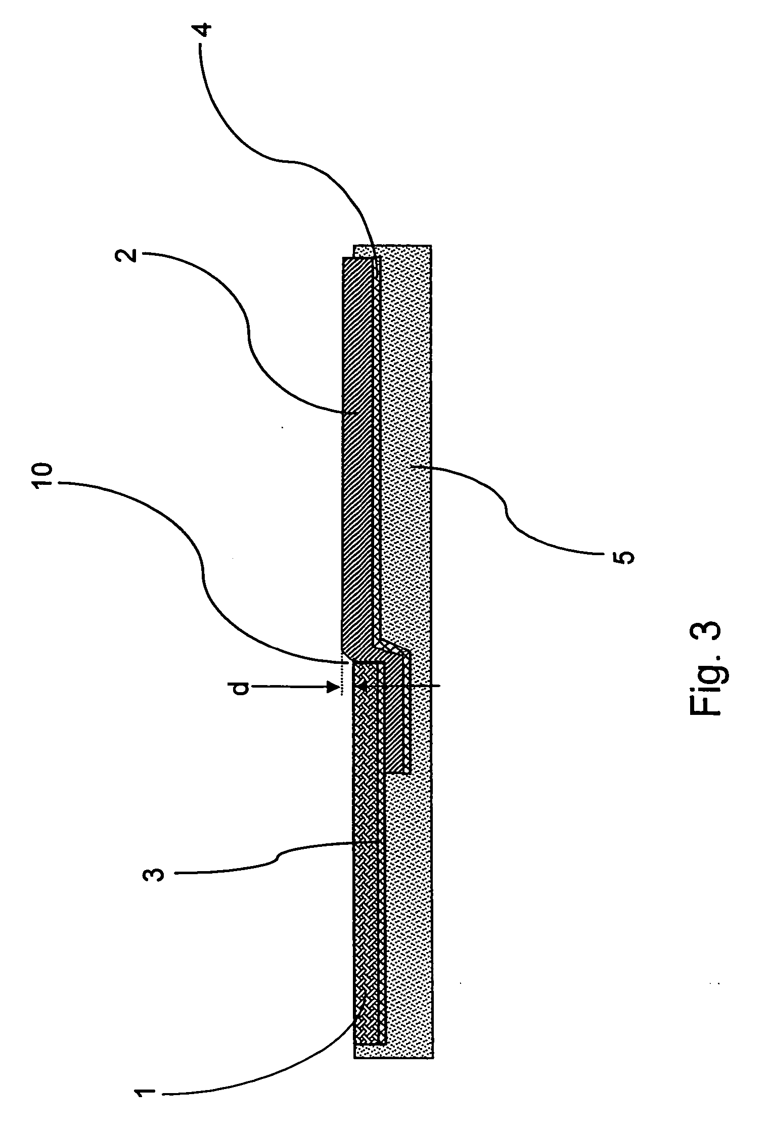
[0005] The present invention provides improved injection molded thin plastic articles with an attractive, surface area of at least two different materials, selected from a wide range of choices, such as real or synthetic leather, woven or non-woven fabric, wood, metal or other semi-rigid surface material. These molded articles have desired combinations of thin dimensions, aesthetics and / or durability with the true feel of the real materials.

Problems solved by technology

The necessity of very thin molded plastic parts for the thin and compact electronic telecommunication and data devices, however, precludes the use of this approach since the thin enclosure parts will not permit a relatively deep channel or groove that hides and protects the joined material seam.
It can also be seen that many of the relatively rigid surface layer materials such as real wood veneers cannot readily be bent or curved at nearly a right angle as required to locate the seam in the bottom of a relatively deep groove.

Method used


Image

  • Molded parts with mixed material surface areas and processes for their production
  • Molded parts with mixed material surface areas and processes for their production
  • Molded parts with mixed material surface areas and processes for their production

Examples


examples

[0057] In an example (Experiment 1) of the product and process according to the invention, a molded polycarbonate substrate is provided with a combination of metal and suede surface areas where the metal is the first material and is set as a stripe across the suede surface area. The metal in this example is anodized aluminum. The metal has a thickness of 0.006 inch (0.15 mm) and was laminated with a thermoplastic adhesive 2 layer film (“2 Layer”) having polyethylene (PE) on one side and polyamide (PA) on other side. This adhesive film has 10 grams (gm) of PE per square meter ( / m2) and 40 gm PA / m2, an overall density of 0.96 gm per cubic centimeter (gm / cm3), and a melting point range of 120 to 125 degree C. This film is laminated to the metal with the PE side against the metal using a flat bed laminator set at 135 degree C. and a lamination pressure of 80 pounds per square inch (psi) (0.55 Mpa). The metal is cut into desired surface area shape, a long stripe, and placed in the mold ...


PUM

PropertyMeasurementUnit
Pressureaaaaaaaaaa
Pressureaaaaaaaaaa
Adhesivityaaaaaaaaaa

Abstract

The present invention provides thin injection molded plastic articles with an attractive, surface area of at least two different materials, such as leather, fabric, wood, metal or other semi-rigid surface material. These molded articles have desired combinations of thin dimensions, aesthetics and / or durability with the true feel of the real materials. The molded plastic articles thus have a plastic substrate component with a front decorative surface having at least two decorative surface areas of layers of different first and second materials having adjacent and connecting surface areas that are generally coplanar or continuous, including at the border line where the two surface layer materials meet. Relative to the front surface, at least a portion of the first material is located on top of and overlaps at least a portion of the second. In the process embodiment two surface material pieces are located in a mold cavity, the two materials together being located so as to each provide a surface area on the front side of the molded part. Optionally there is an adhesive and / or backing material on the back or non-decorative side of one or both surface material pieces. A molding plastic is injected into the mold that contacts and adheres to the back side of the surface material(s) and provides a molded on plastic substrate component. While the molding plastic is sufficiently fluid, pressure is applied to the cavity, preferably in an injection molding process, sufficient to compress and / or form the two different surface materials into a substantially coplanar or continuous surface and press the thicker overlapped area to a necessary depth into the plastic substrate component.

Description

[0001] This invention relates to molded plastic parts having a plastic substrate with a surface layer that comprises different and directly adjacent and connecting surface areas of at least two different surface materials which can be selected from a broad range of flexible or semi-rigid surface materials such as fabrics, leathers, metal foil, wood veneer or similar semi-rigid surface material. This invention is also an efficient process for making these parts where the surface materials are uniformly conformed and adhered to the plastic substrate, and there is a very smooth and aesthetically pleasing border line or transition between the two materials. Parts are produced with good appearance, precise dimensions, thin part cross section and stable, secure material edges. BACKGROUND OF THE INVENTION [0002] In the field of molded plastic parts, there are a number of processes for providing a surface layer or surface insert of a different material fabric, leather, metal, wood or paper,...

Claims


Application Information

Patent Timeline
IPC IPC(8): B32B3/00
CPCY10T428/24802B32B27/12
Inventor WANI, VIJAYABOUGHANEM, RAWADMARCHBANKS, ERICHUS, MICHAEL E.PETERSON, CURTIS E.VAN CONETT, THOMAS E.HOAGLAND, MARY M.LANGMAID, JOSEPH A.
Owner DOW GLOBAL TECH LLC
Learn More